











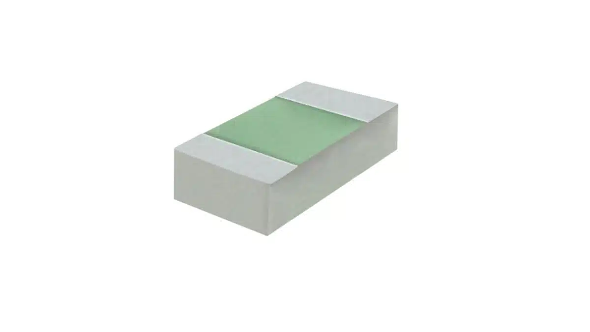
Vishay Intertechnology has introduced the Sfernice CHEP series of thin film chip resistors for RF and microwave designs that need both high-frequency behaviour and substantial continuous power handling in compact surface-mount footprints.
The Vishay SMD resistor series uses an aluminium nitride substrate and is offered in 0402 and 0603 case sizes with flip-chip or wraparound terminations.
Key features and benefits
- High power in small packages: Vishay specifies standard ratings of 1.2 W for the 0402 size and 1.8 W for 0603. When mounted according to the manufacturer’s datasheet guidance, these increase to 1.8 W and 2.8 W respectively.
- Operation to 50 GHz: The 0402 version supports frequencies up to 50 GHz in flip-chip mounting, while a wraparound, active-face-up assembly supports operation up to 20 GHz. The 0603 version is specified to 40 GHz.
- Low parasitic effects: Vishay states LC values as low as , intended to reduce unwanted phase shift, impedance variation and noise at very high frequencies.
- Practical standard footprints: Despite their RF-oriented construction, the parts use familiar 0402 and 0603 land-pattern formats, which can simplify migration from lower-power RF chip-resistor solutions.
- Environmental compatibility: The CHEP series is RoHS-compliant, halogen-free and Vishay Green, with an operating-temperature range from -55 °C to +155 °C.
Technical highlights
| Parameter | CHEP 0402 | CHEP 0603 |
|---|---|---|
| Standard power rating | 1.2 W | 1.8 W |
| Power rating with datasheet-recommended mounting | 1.8 W | 2.8 W |
| Maximum operating frequency | 50 GHz, flip-chip; 20 GHz, wraparound | 40 GHz |
| Resistance range | 20 Ω to 120 Ω | 20 Ω to 120 Ω |
| Standard tolerance | Down to ±1% | Down to ±1% |
| Temperature coefficient | ±100 ppm/°C; ±50 ppm/°C on request | ±100 ppm/°C; ±50 ppm/°C on request |
| Operating-temperature range | -55 °C to +155 °C | -55 °C to +155 °C |
The use of an aluminium nitride substrate is central to the series positioning. AlN is valued in high-power RF layouts for its thermal conductivity, helping transfer dissipated heat into the PCB structure rather than relying on an external heatsink.
CHEP is a dedicated microwave thin-film resistor family rather than a conventional general-purpose chip resistor. As explained in the Thin Film and Metal Film Resistors overview, thin-film construction is typically selected where tolerance, stability, low noise and controlled high-frequency performance matter more than the lowest possible component cost.
Typical applications
Vishay identifies the CHEP series for telecom, connectivity, aerospace and defence hardware where RF bandwidth and power density must coexist.
- LEO satellite terminals and payload electronics
- 5G and emerging 6G network equipment
- Base-station terminals, remote radio units and antenna assemblies
- High-frequency data links and telemetry systems
- Drone communications and guidance electronics
- Phased-array radar systems
- RF power distribution, matching, termination and attenuation networks
At millimetre-wave frequencies, a resistor’s package, orientation, pad geometry and transition into the transmission line can affect circuit response as much as its nominal resistance. This makes dedicated high-frequency resistors relevant in applications where a standard chip resistor may introduce excessive parasitic inductance or capacitance.
Application fit
| Circuit function | Why CHEP may fit | Design focus |
|---|---|---|
| RF terminations | High-frequency operation and low parasitics can support controlled impedance terminations | Match resistor value, pad geometry and transmission-line impedance |
| Attenuators | Tight tolerance and low-reactance construction can help preserve attenuation flatness | Model the complete network, including PCB and connector transitions |
| Bias and damping networks | High dissipation capability can reduce the need for a larger resistor footprint | Verify DC load, RF loading and local temperature rise together |
| RF power stages | High power density can benefit compact transmitter and antenna hardware | Follow the specified mounting configuration and thermal layout |
| Aerospace communications | Broad operating-temperature range supports harsh-environment electronics | Confirm qualification, screening and application-specific requirements with Vishay |
Design-in notes for engineers
- Treat the PCB as part of the component. The highest CHEP power ratings depend on mounting in accordance with Vishay’s datasheet guidance. Copper area, thermal spreading, vias, nearby heat sources and board material directly influence resistor temperature.
- Select termination style early. The stated maximum frequency depends on the assembly method. Flip-chip mounting of the 0402 device is specified to 50 GHz, while wraparound active-face-up mounting is specified to 20 GHz.
- Check the actual RF topology. Nominal resistance alone is insufficient at tens of gigahertz; evaluate the installed part with its pad stack, ground return, transmission line and surrounding components using suitable RF simulation or measurement.
- Separate continuous and pulsed stress. A high continuous power rating does not automatically establish suitability for every pulse, mismatch or transient condition. Confirm pulse capability, derating data and permissible film temperature according to the manufacturer datasheet.
- Account for temperature-driven resistance change. A ±100 ppm/°C TCR limits nominal resistance change with temperature, while the optional ±50 ppm/°C version may be relevant where gain, attenuation or impedance accuracy must remain tightly controlled across the operating range.
- Review layout thermal resistance. Heat from a chip resistor is conducted mainly through its terminations into PCB copper, so land-pattern design and thermal paths should be considered alongside the electrical design. See Resistivity and Thermal Resistance for practical thermal considerations.
Further reading
- Thin Film and Metal Film Resistors
- Resistor Technology Selection and Benchmark Guidelines
- SMD Chip Resistors: Types, Packages, Ratings and Design Guide
- Role of High-Frequency Resistors in 5G Systems
Source
This article is based on the Vishay Intertechnology press release for the Sfernice CHEP high-frequency, high-power thin film chip resistor series. Engineers should consult the current manufacturer datasheet and associated documentation before final component qualification, PCB release or production design approval.












