


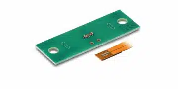


Stackpole Electronics has introduced the RNCQ series of high-frequency thin film chip resistors optimized for RF and microwave circuits up to 50 GHz.
Designed on a high-purity substrate with advanced thin film processes, these parts target applications where impedance control, low loss, and repeatable performance over frequency are critical. For design engineers and purchasing teams, the series aims to bridge the gap between traditional thin film chip resistors and dedicated RF components by adding frequency-domain characterization and modeling data.
Key features and benefits
- High-frequency operation up to 50 GHz – The RNCQ series is explicitly engineered for RF and microwave circuits up to 50 GHz, which puts it into the range relevant for millimeter-wave, advanced 5G, and high-end test and measurement designs.
- Thin film technology on high-purity substrate – The resistors use advanced thin film technology deposited on a high-purity substrate, supporting low parasitic inductance and capacitance, and enabling stable impedance behavior over a wide frequency range.
- Proprietary design and manufacturing processes – Stackpole highlights proprietary design and process controls aimed at achieving stable, reliable performance under demanding high-frequency conditions, which is important for repeatability across lots and over temperature.
- Frequency-domain characterization support – For common EIA chip sizes and resistance values, Stackpole provides impedance-versus-frequency curves and S‑parameter data (including insertion and reflection loss), which significantly simplifies RF design-in and simulation model creation.
- Stable performance for demanding RF environments – The overall combination of substrate choice, thin film stack, and process control is intended to keep impedance and loss characteristics predictable when the resistor is used as a termination, attenuation element, bias feed, or matching component in RF chains.
In practice, the availability of measured S‑parameters and impedance curves allows engineers to move beyond simple DC resistance and treat the RNCQ as a small passive RF component with known behavior over frequency, reducing the need for in-house characterization in early design phases.
Typical applications
The RNCQ series targets RF and microwave designs where both DC precision and RF behavior matter. Typical application areas mentioned by Stackpole include:
- RF and microwave communications – General RF front ends, gain stages, and IF sections where chip resistors are used for gain setting, feedback, biasing, and terminations in the hundreds of MHz up into the multi‑GHz region.
- 5G infrastructure and systems – Base stations, small cells, and active antenna units where resistors must maintain consistent impedance at sub‑6 GHz and mmWave frequencies, including 28 GHz and beyond.
- Satellite communications – RF chains in satellite transponders, ground stations, and phased array front ends, where high-frequency performance and long-term stability are critical under environmental stress.
- Precision RF and microwave test equipment – Signal generators, spectrum and network analyzers, power meters, and RF fixtures that rely on well-characterized resistive elements for attenuators, terminations, and calibration standards.
Beyond these, the same component attributes are useful in radar, instrumentation amplifiers with RF content, and broadband measurement setups where parasitic effects of general-purpose chip resistors become a limiting factor.
Technical highlights
The press release focuses on the high-frequency behavior and supporting data rather than listing detailed numerical ratings, which are expected to be specified in the RNCQ datasheet. For actual design-in, engineers should refer to the manufacturer documentation for precise values of resistance range, TCR, tolerance, power rating, and package sizes.
Typical technical aspects of such a high-frequency thin film chip resistor family include:
- Resistance range – A range suitable for terminations (for example around 50 Ω and 75 Ω), matching networks, and bias networks; exact resistance values are according to the manufacturer datasheet.
- TCR and tolerance options – Thin film technology generally supports low TCR and tight tolerance options, which help maintain gain, impedance, and calibration accuracy over temperature; specific figures are according to the manufacturer datasheet.
- Package sizes – Common SMD chip resistor packages (for example 0402, 0603, etc.) typically used in RF layouts; supported sizes are according to the manufacturer datasheet.
- Power rating and operating temperature – Power dissipation and allowable operating temperature range are defined in the RNCQ datasheet and should be checked carefully for each case, especially at high ambient temperatures and high RF power levels.
From an RF point of view, the key differentiator is that Stackpole provides both impedance‑versus‑frequency curves and S‑parameter data (S11, S21) for typical combinations of size and resistance. This allows straightforward import into RF simulators, enabling engineers to include the resistor’s real behavior, including parasitic capacitance and inductance, insertion loss, and return loss, into their system models.
Frequency-domain support data
The press release highlights several types of supporting data curated for RF and microwave use.
- Impedance versus frequency curves – Show how the magnitude and possibly phase of impedance change with frequency, which helps identify self-resonance and the useful flat region for a given value and package.
- S‑parameters for insertion loss – Provide information about how much signal power is lost when passing through or terminated by the resistor, important for cascaded RF stages and filter networks.
- S‑parameters for reflection loss – Describe how much signal is reflected (mismatch) at the resistor terminals when used as a termination or part of a matching network, which directly impacts VSWR and return loss.
This level of data is especially valuable when moving to frequencies above a few GHz, where layout and parasitics make simple lumped models inadequate and where chip resistors can become inductive or capacitive depending on frequency.
Summary of technical positioning
| Aspect | RNCQ positioning (qualitative) |
|---|---|
| Frequency range | Up to 50 GHz for RF and microwave circuits |
| Technology | Thin film on high-purity substrate |
| Focus | High-frequency stability and predictable RF behavior |
| Support data | Impedance vs. frequency and S‑parameters |
| Typical use | RF terminations, matching, biasing, test and measurement |
All detailed numerical specs, such as derating curves or maximum working voltage, should be taken from the official RNCQ datasheet to avoid over‑stressing components in demanding RF environments.
Design-in notes for engineers
From an engineering perspective, the RNCQ series is interesting primarily because it combines standard thin film chip resistor handling with RF‑appropriate characterization. This section outlines practical design-in considerations based on the nature of high-frequency thin film chip resistors.
- Treat the resistor as an RF component, not just a DC element – At frequencies approaching tens of GHz, even small chip resistors exhibit parasitic inductance and capacitance; the provided impedance and S‑parameters should be used to build accurate models in circuit and EM simulators.
- Package size versus frequency – Smaller packages generally support higher frequencies with less parasitic inductance; when choosing between footprints, use the manufacturer’s impedance-versus-frequency curves to ensure that the self‑resonant point and impedance flatness align with your target band.
- Layout and grounding – For terminations and matching networks, pay careful attention to land pattern geometry, via placement, and ground reference; the resistor performance at 50 GHz is strongly influenced by PCB stack‑up and launch design.
- Power handling and thermal limits – RF power can cause significant local heating due to both I²R loss and dielectric loss in surrounding structures; the safe operating area and power derating for each package must be taken from the RNCQ datasheet and combined with thermal simulation or measurement in the target layout.
- Bias networks and decoupling – When using RNCQ devices in bias tees or bias feeds, ensure that the resistor maintains the required resistance and low reflection across the relevant RF band while still meeting DC bias requirements; check S‑parameter data around both fundamental and harmonic frequencies.
- Test equipment and calibration arrays – In test equipment, using resistors with well‑documented S‑parameters simplifies calibration and uncertainty analysis, as the frequency-dependent loss and reflection behavior of each element can be included in the error budget.
- Design for manufacturability – Since the parts are thin film chip resistors in standard packages, they are compatible with standard SMT assembly processes; nevertheless, RF boards often use low‑loss laminates and fine geometries that require close coordination with the PCB fabricator to maintain controlled impedance up to 50 GHz.
For engineers working on 5G infrastructure, satellite links, or high-speed measurement systems, the main value lies in having resistor components whose RF behavior is as predictable as that of dedicated RF passives, reducing the risk that seemingly simple resistors become performance bottlenecks at high frequencies.
Source
This article is based on information provided in the official Stackpole Electronics press release announcing the RNCQ high-frequency thin film chip resistor series, complemented by general design considerations for RF and microwave resistive components.