


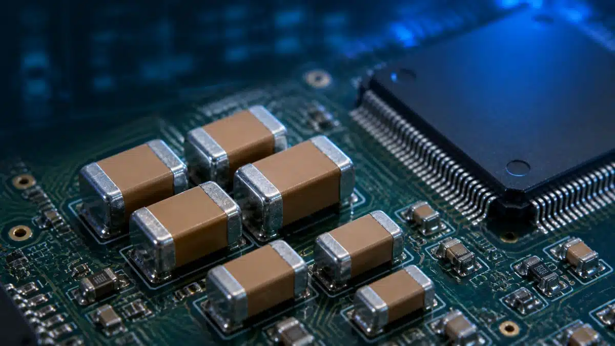
Samsung Electro-Mechanics has introduced an automotive-grade multilayer ceramic capacitor (MLCC) that combines 100 µF capacitance and 4 V rating in a 1206 (3.2 × 1.6 mm) package with X7T temperature characteristics.
This Samsung Electro-Mechanics ultra‑high capacitance MLCC ceramic capacitor is aimed at power distribution around advanced automotive SoCs and sensors, where board space is tight but transient current demands are rising. For design teams, it offers a way to consolidate decoupling networks and reduce capacitor counts in ADAS and other high‑integration ECUs while staying within AEC‑Q200 constraints.
Key features and benefits
- Ultra‑high capacitance in 1206 size
100 µF capacitance in a 1206 (3216 metric) MLCC footprint supports bulk decoupling and low‑frequency noise suppression very close to high‑current IC pins, where larger can or polymer capacitors may not fit. - Automotive‑grade and AEC‑Q200 compliant lineup
The new 1206, 100 µF, 4 V part is part of a broader AEC‑Q200 automotive portfolio spanning 0402 to 1210 sizes and 2.5 to 6.3 V ratings, simplifying multi‑rail designs on the same BOM and supplier base. - X7T temperature characteristic
X7T specifies a working temperature range from −55 °C to 125 °C with a defined capacitance change window, suitable for typical under‑hood and in‑cabin automotive conditions where ambient and self‑heating combine. - Space and cost consolidation potential
By replacing parallel banks of lower‑capacitance MLCCs with fewer 100 µF parts, designers can free PCB area, simplify assembly, and reduce placement count while maintaining similar effective capacitance in application. - Extended lineup in 1210 package
In parallel with the 1206 device, Samsung Electro‑Mechanics offers 1210 MLCCs with 100 µF / 6.3 V and 220 µF / 2.5 V ratings, including high bending strength versions intended for mechanically demanding automotive PCBs. - High bending strength options
For zones exposed to board flex (edge connectors, large modules, heavy components), the 1210 high bending strength versions are designed to better tolerate mechanical stress and reduce the risk of ceramic cracking during assembly and vehicle lifetime.
Typical applications
Automotive systems increasingly rely on high‑performance SoCs, radar and camera modules, and dense power management stages, all of which require stable local energy storage and low impedance power rails. The new 1206, 100 µF MLCC is positioned mainly as a high‑capacitance decoupling and buffering device in such environments.
Typical application areas include:
- ADAS ECUs with high‑speed SoCs, where local bulk decoupling is needed close to the processor core supply rails.
- Radar and camera modules, especially where compact board outlines constrain the use of larger electrolytic or hybrid capacitors.
- Power delivery for high‑speed communication interfaces and domain controllers that experience rapid load steps.
- Automotive infotainment, instrument clusters, and central compute architectures with multi‑rail power trees that benefit from a unified automotive MLCC family.
- Any automotive board where high capacitance is required in a limited footprint and a wide temperature range from −55 °C to 125 °C is expected.
The associated 1210‑size 100 µF / 6.3 V and 220 µF / 2.5 V devices extend these use cases towards higher voltage rails or larger energy buffering, for example in point‑of‑load regulators and low‑voltage power stages.
Technical highlights
The press release highlights a combination of miniaturization and capacitance increase supported by proprietary ceramic and electrode fine‑particle technologies and ultra‑precision processing. In practice, this translates to very thin dielectric layers and finely controlled internal electrode structures, enabling 100 µF in a 1206 footprint within automotive qualification constraints.
Product lineup overview
The table below summarizes the key products mentioned in the announcement. Exact electrical characteristics, derating curves, and reliability data should be confirmed in the respective manufacturer datasheets.
| Part number | Size (inch / mm) | Capacitance | Rated voltage | TCC | Notes |
|---|---|---|---|---|---|
| CL31Z107MRK6PN# | 1206 / 3216 | 100 µF | 4 V | X7T | Automotive, standard |
| CL32Z107MQV6PJ# | 1210 / 3225 | 100 µF | 6.3 V | X7T | High bending strength |
| CL32Z227MSV6PJ# | 1210 / 3225 | 220 µF | 2.5 V | X7T | High bending strength |
The X7T characteristic supports operation from −55 °C to 125 °C, which is compatible with a wide range of in‑vehicle locations. High bending strength variants in 1210 are particularly relevant for large or mechanically exposed boards where MLCC cracking and latent faults are a concern and where board bending tests per AEC‑Q200 are critical.
Design‑in notes for engineers
From a design perspective, ultra‑high capacitance MLCCs in small packages behave differently from lower‑value capacitors and require careful attention to derating, DC bias effects, and mechanical integration. The following points can help when designing in the new 1206 device and its 1210 companions:
- Voltage derating and DC bias behavior
- For a 4 V rated, 100 µF MLCC, many automotive designers will derate the operating voltage (for example running it well below the nominal rating) to account for DC bias capacitance loss and long‑term reliability; the actual recommended operating margin should be taken from the manufacturer datasheet and application notes.
- Capacitance in high‑cap MLCCs can drop significantly under DC bias and temperature; measure or simulate the effective capacitance under real operating conditions (voltage, temperature, AC ripple) rather than relying purely on nominal values.
- Temperature performance
- X7T guarantees operation from −55 °C to 125 °C with defined capacitance variation; in practice, this allows placement near hot ICs and within engine‑bay or central compute modules, provided local thermal management is adequate.
- Evaluate self‑heating due to ripple currents, especially when using these parts as bulk decoupling on rails with high dynamic load, and cross‑check permissible ripple current and dissipation factor according to the datasheet.
- Mechanical robustness and PCB layout
- On boards subject to mechanical stress, vibration, or flexing (typical in automotive modules), consider using the high bending strength 1210 variants and follow best‑practice land patterns to reduce tensile stress on the terminations.
- Avoid placing high‑cap MLCCs across PCB break lines, near mounting holes, or in locations where automated handling may cause flex; when unavoidable, consult the manufacturer’s recommended pad shapes and support measures (for example, underfill or flexible terminations where applicable).
- Replacement of electrolytic capacitors
- In some low‑voltage rails, the 100 µF 1206 device can replace small aluminum electrolytic capacitors, reducing height and improving high‑frequency performance, but the effective capacitance under bias and the ripple current capability must be checked against the target application.
- When replacing electrolytics, validate start‑up behavior, control loop stability, and transient response using the MLCC’s impedance profile over frequency, taken from manufacturer characterization data.
- EMC and power integrity considerations
- High‑cap MLCCs provide low ESR and ESL, which is beneficial for high‑frequency decoupling and EMC, but they also can interact with power stage inductances to form resonances; combine them with smaller‑value capacitors or damping where necessary.
- For ADAS SoCs and radar front ends, place the 1206 100 µF part as close as possible to the main power entry to the IC or module, and use short, wide traces or planes to minimize loop inductance and voltage dips during load steps.
- Qualification and documentation
- Ensure that the selected part numbers meet the required AEC‑Q200 test conditions for the target application and vehicle OEM; refer to the datasheet and qualification reports for details on life test, temperature cycling, and mechanical testing.
- Document any derating strategy, measured effective capacitance, and mechanical layout constraints in the project design rules, so that future layout iterations and derivative designs keep the same robustness margins.
Source
This article is based on information provided in the official Samsung Electro‑Mechanics product news release on automotive ultra‑high‑capacitance MLCCs and the associated product pages and datasheets on the manufacturer’s website, with additional independent editorial context for design engineers.


