Passive Components Blog
No Result
View All Result
  • Home
  • NewsFilter
    • All
    • Aerospace & Defence
    • Antenna
    • Applications
    • Automotive
    • Capacitors
    • Circuit Protection Devices
    • electro-mechanical news
    • Filters
    • Fuses
    • Inductors
    • Industrial
    • Integrated Passives
    • inter-connect news
    • Market & Supply Chain
    • Market Insights
    • Medical
    • Modelling and Simulation
    • New Materials & Supply
    • New Technologies
    • Non-linear Passives
    • Oscillators
    • Passive Sensors News
    • Resistors
    • RF & Microwave
    • Telecommunication
    • Weekly Digest

    TDK Extends SMT Gate Drive Transformers to 1000 V

    Non-Linear MLCC Class II Capacitor Measurements Challenges

    Researchers Demonstrated HfO Anti-Ferroelectric Flexible Capacitors

    Connector Industry Achieves Double-Digit Growth

    Stackpole Unveils Metal Element High Current Chip Jumpers

    Common Mistakes in Flyback Transformer Specs

    Vishay Releases Miniature SMD Trimmers for Harsh Environments

    Würth Elektronik Releases Push-Button and Main Switches

    Littelfuse Unveils High-Precision TMR Angle Magnetic Sensors

    Trending Tags

    • Ripple Current
    • RF
    • Leakage Current
    • Tantalum vs Ceramic
    • Snubber
    • Low ESR
    • Feedthrough
    • Derating
    • Dielectric Constant
    • New Products
    • Market Reports
  • VideoFilter
    • All
    • Antenna videos
    • Capacitor videos
    • Circuit Protection Video
    • Filter videos
    • Fuse videos
    • Inductor videos
    • Inter-Connect Video
    • Non-linear passives videos
    • Oscillator videos
    • Passive sensors videos
    • Resistor videos

    Non-Linear MLCC Class II Capacitor Measurements Challenges

    Percolation Phenomenon and Reliability of Molded Power Inductors in DC/DC converters

    Root Causes and Effects of DC Bias and AC in Ceramic Capacitors

    How to Calculate the Output Capacitor for a Switching Power Supply

    Switched Capacitor Converter Explained

    Understanding Inductor Dot Markings and Their Application in LTspice

    Accelerating Full Bridge LLC Resonant Converter Design with Frenetic AI

    Understanding Switched Capacitor Converters

    Coupled Inductors Circuit Model and Examples of its Applications

    Trending Tags

    • Capacitors explained
    • Inductors explained
    • Resistors explained
    • Filters explained
    • Application Video Guidelines
    • EMC
    • New Products
    • Ripple Current
    • Simulation
    • Tantalum vs Ceramic
  • Knowledge Blog
  • Suppliers
    • Who is Who
  • Events
No Result
View All Result
Passive Components Blog
No Result
View All Result

Würth Elektronik Expands Online Simulation Tool with Inductor DC Bias Losses

22.1.2024
Reading Time: 2 mins read
A A

Würth Elektronik’s online design platform, REDEXPERT, known as having the most accurate ac losses for power inductors under operating conditions, now includes the effects of dc bias on the ac losses.

It is a well-established but little understood fact that ac core losses increase when the ac ripple is dc biased. This is the normal operating condition for power converters like the buck regulator.

RelatedPosts

Würth Elektronik Releases Push-Button and Main Switches

Percolation Phenomenon and Reliability of Molded Power Inductors in DC/DC converters

Würth Elektronik Offers Accessory Humidity Sensor Filter Cap

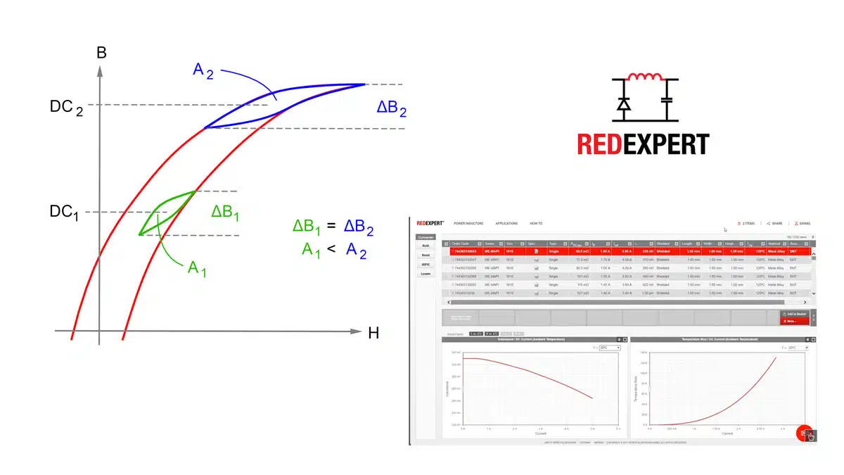
Normal intuition says that dc bias does not increase ac cores losses because it is a static shift. However, those who have experienced unexpected temperature rise and investigated, have found that the dc bias does in fact change the core’s ac losses. This can be understood by realizing the minor BH loop from the ac ripple follows along the general form of the major BH loop.

The permeability and hence inductance are proportional to the slope of the curves. As the minor loop move closer towards saturation, the minor loop’s slope decreases. This decreases inductance resulting in increased ripple current. With the decreased slope and the BH loop becomes elongated, meaning more losses.

Thus, as dc bias is increased, the inductance will eventually start to decrease as it moves towards saturation which will in turn increase the ripple and the ac losses. The minor BH loop representing the hysteresis losses increases.

REDEXPERT now includes this small but significant change for even more accurate ac losses.

Related

Source: Würth Elektronik

Recent Posts

TDK Extends SMT Gate Drive Transformers to 1000 V

20.8.2025
8

Common Mistakes in Flyback Transformer Specs

15.8.2025
23

Littelfuse Unveils High-Precision TMR Angle Magnetic Sensors

13.8.2025
9

High Voltage MLCCs Meeting the Growing Demand for Efficiency in Power Conversion

12.8.2025
118

Bourns Releases High Power High Ripple Chokes

8.8.2025
33

KYOCERA AVX Releases Hermaphroditic WTW and WTB Connectors

8.8.2025
15

Radiation Tolerance of Tantalum and Ceramic Capacitors

8.8.2025
72

Percolation Phenomenon and Reliability of Molded Power Inductors in DC/DC converters

6.8.2025
42

Vishay Releases High Saturation 180C Automotive Inductors

6.8.2025
26

Additive Manufacturing of Mn-Zn Ferrite Planar Inductors

4.8.2025
28

Upcoming Events

Aug 27
17:00 - 18:00 CEST

Capacitor Assemblies for High-Power Circuit Designs

Sep 3
15:30 - 17:30 CEST

How to Choose Your Magnetic Supplier

Sep 16
17:00 - 18:00 CEST

EMI Shielding Challenges

Sep 22
September 22 @ 13:00 - September 25 @ 15:15 EDT

Pre Cap Visual Inspection per Mil-Std-883 (TM 2017)

Sep 30
September 30 @ 12:00 - October 2 @ 14:00 EDT

MIL-Std-883 TM 2010

View Calendar

Popular Posts

  • Buck Converter Design and Calculation

    0 shares
    Share 0 Tweet 0
  • Boost Converter Design and Calculation

    0 shares
    Share 0 Tweet 0
  • Flyback Converter Design and Calculation

    0 shares
    Share 0 Tweet 0
  • LLC Resonant Converter Design and Calculation

    0 shares
    Share 0 Tweet 0
  • What is a Dielectric Constant and DF of Plastic Materials?

    4 shares
    Share 4 Tweet 0
  • Ripple Current and its Effects on the Performance of Capacitors

    3 shares
    Share 3 Tweet 0
  • Dual Active Bridge (DAB) Topology Explained

    0 shares
    Share 0 Tweet 0
  • How to Design an Inductor

    0 shares
    Share 0 Tweet 0
  • MLCC Case Sizes Standards Explained

    0 shares
    Share 0 Tweet 0
  • Core Materials, Permeability and Their Losses

    0 shares
    Share 0 Tweet 0

Newsletter Subscription


Passive Components Blog

© EPCI - Leading Passive Components Educational and Information Site

  • Home
  • Privacy Policy
  • EPCI Membership & Advertisement
  • About

No Result
View All Result
  • Home
  • Knowledge Blog
  • Premium Suppliers

© EPCI - Leading Passive Components Educational and Information Site

This website uses cookies. By continuing to use this website you are giving consent to cookies being used. Visit our Privacy and Cookie Policy.
Go to mobile version