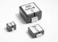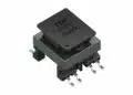







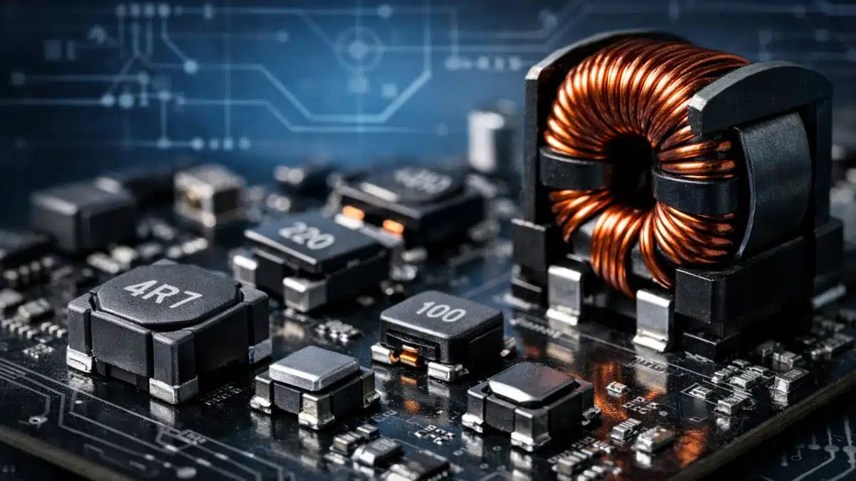
Higher switching frequencies and tighter power-density targets are reshaping inductor design across server, industrial and automotive power electronics. NANOMET soft magnetic material from YAGEO KEMET addresses that shift by combining high saturation capability, temperature-stable behavior and reduced dependence on large external air gaps, making it relevant for compact inductors in high-current and high-frequency converter stages.
As converter designers push beyond traditional ferrite comfort zones, the limiting factor is increasingly the complete inductor loss balance rather than a single magnetic parameter. In that context, YAGEO NANOMET stands out as a material platform aimed at improving the trade-off between core loss, copper loss, size and EMI.
Why this material matters
The move to GaN- and SiC-based power conversion has increased the pressure on magnetic components to deliver more power in less volume. In many designs, switching frequencies now extend into the several-hundred-kilohertz range, while multiphase buck regulators for high-performance processors operate around 1 MHz.
That trend changes the way inductors must be evaluated. Downsizing a magnetic component with a conventional material often increases core loss and makes thermal management harder, especially where magnetic flux density and current ripple are both high. A more suitable core material can therefore unlock not just smaller magnetics, but a better system-level efficiency and cooling balance.
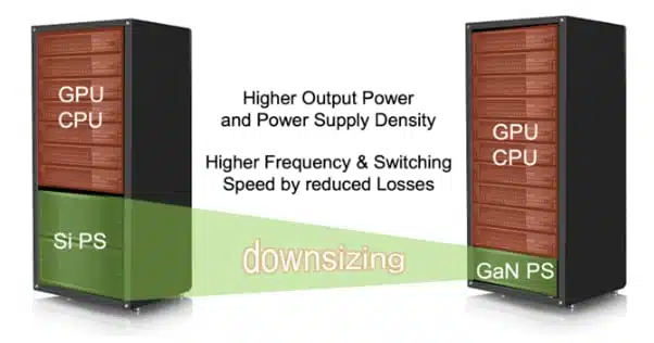
Figure 1. Increasing power density in modern server applications.
Core behavior and practical implications
The key material parameters are permeability, saturation behavior and frequency-related loss. Permeability determines how much inductance can be achieved for a given geometry, while saturation behavior defines how far the inductor can be pushed before inductance starts to collapse under current load.
In practical power inductor design, ferrites often require a discrete air gap to avoid abrupt saturation. That solves one problem, but creates others: flux leakage, fringing losses, EMI challenges and added volume. A material with softer saturation behavior and a more distributed internal gap structure reduces those penalties.
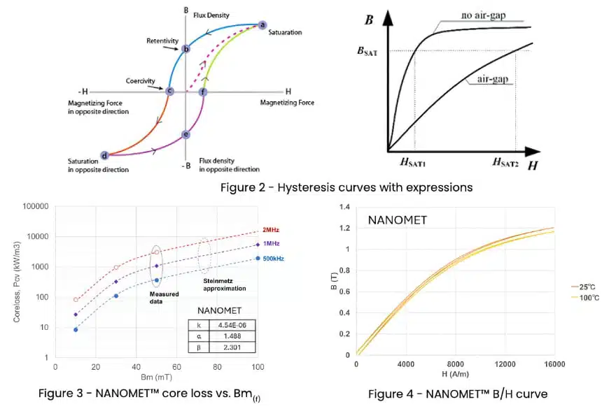
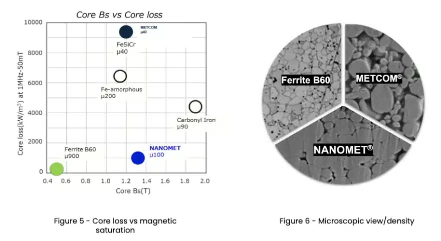
The core-loss plot is especially relevant in high-frequency converter design, while the B/H curve shows why the material can be attractive where designers need usable inductance under high current without a strongly leaky external gap.
Key features and benefits
- High saturation capability supports demanding DC bias conditions in compact inductors.
- Temperature-stable magnetic behavior helps maintain predictable inductance under thermal stress.
- A practical permeability level around 100 suits power inductor design without the large external air gap typically used in ferrite implementations.
- Reduced air-gap dependence lowers fringing-field effects and can improve EMI behavior.
- Shorter winding structures and fewer turns can reduce DCR and copper losses.
- The material is suited to both low-inductance high-current parts and larger high-power choke designs.
Material positioning against ferrite and metal composite
NANOMET does not replace every existing soft magnetic material, but it does fill an important performance window between ferrite and conventional metal composite solutions. Ferrites remain attractive where very low core loss dominates the design target, while metal composites remain useful in some compact molded designs. NANOMET becomes particularly relevant where high saturation margin, manageable core loss and compact size must all be met together.
| Material family | Ferrites | Metal composite | NANOMET |
|---|---|---|---|
| Composition | Mn-Zn | FeSiCr | FeSiBPCuCr |
| Process | Powder mold sintering | Powder mold curing | Hot mold |
| Permeability μ | 900, usually reduced by gap in use | 25 | 100 |
| Bc | 0.5 T | 1.2 T | 1.3 T |
| μ versus temperature | Not stable | Stable | Stable |
| Relative core loss | Low | High | Mid |
Air-gap reduction as an EMI and thermal advantage
Large external air gaps are often accepted as a normal part of ferrite inductor design, yet they are also a common source of local field leakage. That leakage can drive fringing losses in nearby conductors and increase radiated or coupled noise in dense converter layouts.
Every core material has process foundations that lead the way to mechanical inductor designs. While typical metal composite materials can be processed to form a core around a coil specifically for surface-mounted power inductors, the process for ferrites and NANOMET™ dictates forming a solid block shape first and assembling the coil afterwards. The process conditions of those materials require enormous pressure and heat that would soften electrical isolation materials and can cause deformation, which is called “Hot Press Molding” technology.

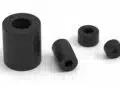
Figure 7 – Typical NANOMET™ core shapes used that can be manufactured
Metal composite and NANOMET™ inductors have a built-in airgap structure in the material that ensures each metal powder grain is coated with a Silicon shell, which represents the magnetic gap. Ferrite designs typically need to operate with an air gap to avoid saturation by applied current. An air gap allows the magnetic field to leak through the whole design and can cause EMI challenges. The field leakage also causes fringing losses to structures close to the winding. In high-power designs, this can introduce a significant amount of heat in the conductor.
With some core designs, even metal composite or NANOMET™ component structures require minimal airgaps to increase the saturation capability or cater for the required mechanical conditions that the application demands and the core assembly process dictates. In any case, the gap is smaller with iron-based silicon-coated materials, and the impact of EMI emission and fringing losses is much less.
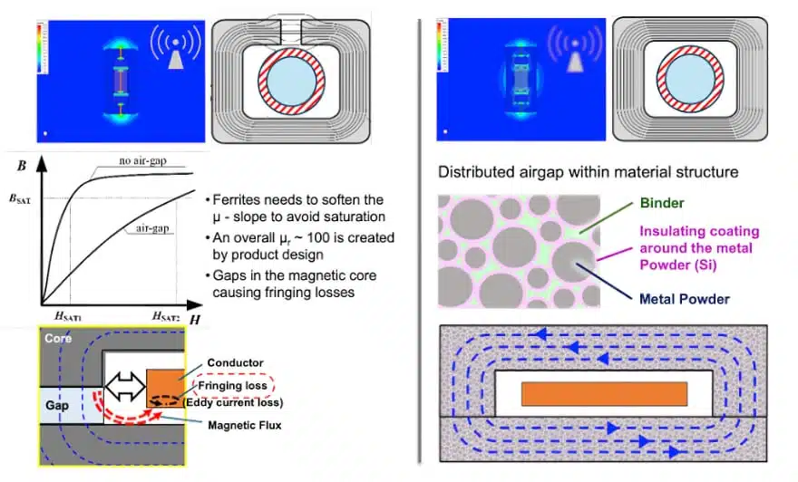
Figure 8. Influence of air gaps in power inductor designs.
This explains why air-gap architecture is not just a material-science detail. In practical designs, a smaller or internally distributed gap can reduce both EMI and localized heating near the winding, particularly in high-current storage inductors.
Typical applications
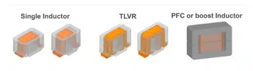
The material is relevant across several distinct inductor classes. It spans both low-inductance, very high-current parts and higher-inductance, higher-power choke designs:
- Multiphase buck regulator power beads for CPUs and GPUs.
- TLVR inductors for faster transient response in processor power delivery.
- PFC and boost inductors in higher-power AC/DC conversion.
- PCB-mount SMD power inductors for dense local power stages.
#1 Power bead case study: 90 nH in a server VR environment
In low-inductance, high-current server regulator stages, inductor volume, DCR and saturation current all directly affect efficiency and thermal headroom. A 90 nH comparison shows that a NANOMET power bead in the same basic footprint class can deliver lower DCR, lower total loss and a lower component height than a ferrite alternative, while also improving saturation current.
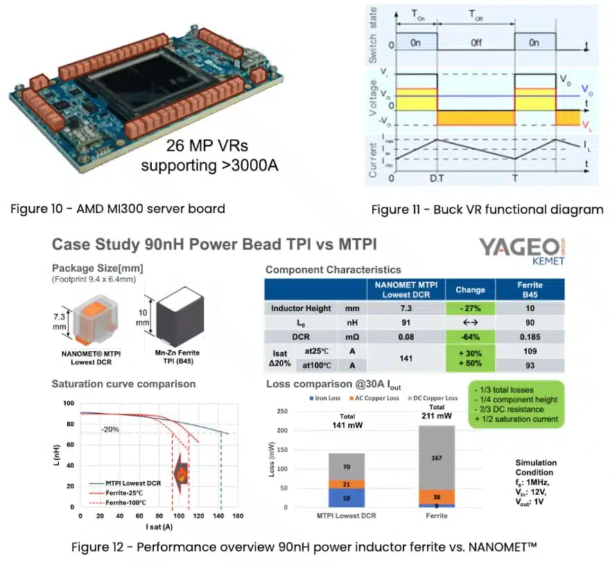
The relevant engineering takeaway is that total inductor loss matters more than isolated core loss. Even where ferrite may retain an advantage in one loss component, the shorter winding and lower copper losses of a NANOMET-based design can produce a better overall result, especially as current rises.
#2 TLVR case study: faster transient response with smaller magnetics
Transient load voltage regulator architectures are designed for extremely fast current slew during CPU and GPU load steps. In this environment, inductors must support both dynamic response and manageable efficiency.
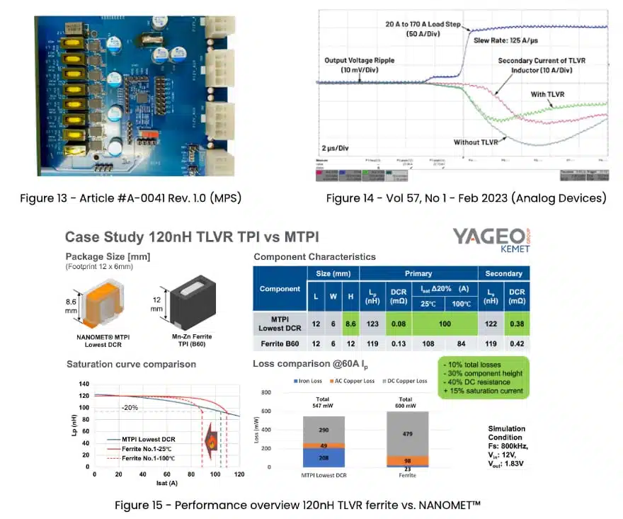
The comparison points to lower DCR and lower profile for the NANOMET version, alongside a favorable total-loss result. This makes the material attractive where board density and transient performance must improve together without accepting a large EMI penalty from a gapped ferrite structure.
#3 PFC choke case study: compact magnetics at higher power
The material case becomes even more interesting in larger front-end magnetics. In PFC or boost inductors, designers need to control core loss while also meeting mechanical volume and thermal limits.
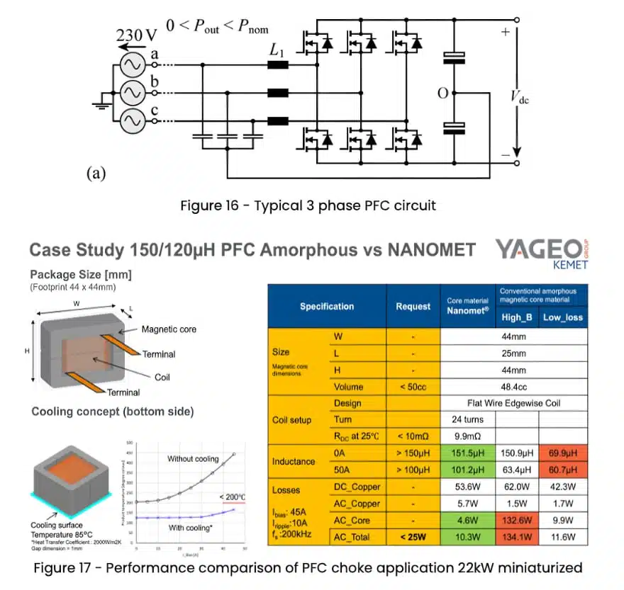
In this application space, the attraction of NANOMET is its ability to support compact choke geometry while still meeting inductance and loss targets at elevated switching frequency. The data also reinforces a realistic design rule: even with a strong core material, winding losses remain important and must be paired with an effective thermal extraction path.
#4 SMD inductor case study: 150 nH PCB-mount design
For compact local power conversion, DCR and saturation current are often the first two filters in part selection. In the 150 nH SMD comparison, the NANOMET example achieves much lower resistance and significantly higher saturation current than the compared METCOM parts at similar nominal inductance.
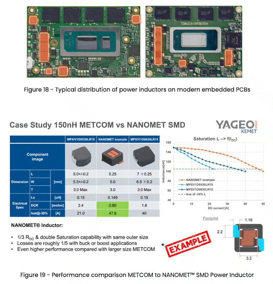
This makes the material relevant not only for very high-end server hardware, but also for smaller DC/DC stages where every square millimeter and every milliohm matter.
Design-in notes for engineers
- Evaluate performance at the complete inductor level, not only from raw core-loss curves.
- Compare DCR, saturation current, package height and EMI impact together when benchmarking against ferrite designs.
- In high-current designs, expect copper losses to dominate more strongly as load rises, which can favor shorter winding structures.
- In PFC and boost applications, include the thermal path in the first design iteration rather than treating it as a later mechanical fix.
- Confirm exact ratings, dimensions and qualification details in the latest datasheet when selecting production parts, especially where the article examples are based on comparison platforms rather than a full commercial part-number table.
Source
This article is based on an official YAGEO KEMET technical release covering NANOMET soft magnetic material, its material characteristics and four application comparisons spanning power beads, TLVR inductors, PFC chokes and compact SMD power inductors.