Passive Components Blog
No Result
View All Result
  • Home
  • NewsFilter
    • All
    • Aerospace & Defence
    • Antenna
    • Applications
    • Automotive
    • Capacitors
    • Circuit Protection Devices
    • electro-mechanical news
    • Filters
    • Fuses
    • Inductors
    • Industrial
    • Integrated Passives
    • inter-connect news
    • Market & Supply Chain
    • Market Insights
    • Medical
    • Modelling and Simulation
    • New Materials & Supply
    • New Technologies
    • Non-linear Passives
    • Oscillators
    • Passive Sensors News
    • Resistors
    • RF & Microwave
    • Telecommunication
    • Weekly Digest

    Vishay Expanded Inductor Portfolio With More Than 2000 Stock Items 

    Paumanok Releases Capacitor Foils Market Report 2025-2030

    Modelithics Welcomes CapV as a Sponsoring MVP

    Wk 40 Electronics Supply Chain Digest

    Benefits of Tantalum Powder Stress–Strain Curve Evaluation vs Conventional Wet Test

    Electrolyte Selection and Performance in Supercapacitors

    Connector PCB Design Challenges

    Researchers Demonstrated High Energy Ceramic Capacitors Stable in Wide Temperature Range

    Stackpole Offers High Voltage Plate Resistors up to 40KV

    Trending Tags

    • Ripple Current
    • RF
    • Leakage Current
    • Tantalum vs Ceramic
    • Snubber
    • Low ESR
    • Feedthrough
    • Derating
    • Dielectric Constant
    • New Products
    • Market Reports
  • VideoFilter
    • All
    • Antenna videos
    • Capacitor videos
    • Circuit Protection Video
    • Filter videos
    • Fuse videos
    • Inductor videos
    • Inter-Connect Video
    • Non-linear passives videos
    • Oscillator videos
    • Passive sensors videos
    • Resistor videos

    Connector PCB Design Challenges

    Efficient Power Converters: Duty Cycle vs Conduction Losses

    Ripple Steering in Coupled Inductors: SEPIC Case

    SEPIC Converter with Coupled and Uncoupled Inductors

    Coupled Inductors in SEPIC versus Flyback Converters

    Non-Linear MLCC Class II Capacitor Measurements Challenges

    Percolation Phenomenon and Reliability of Molded Power Inductors in DC/DC converters

    Root Causes and Effects of DC Bias and AC in Ceramic Capacitors

    How to Calculate the Output Capacitor for a Switching Power Supply

    Trending Tags

    • Capacitors explained
    • Inductors explained
    • Resistors explained
    • Filters explained
    • Application Video Guidelines
    • EMC
    • New Products
    • Ripple Current
    • Simulation
    • Tantalum vs Ceramic
  • Knowledge Blog
  • Suppliers
    • Who is Who
  • Events
No Result
View All Result
Passive Components Blog
No Result
View All Result

Applications of Exciter Discharge Resistors

6.11.2017
Reading Time: 4 mins read
A A

source: AZO Materials news

An exciter in a synchronous generator is used to deliver the DC supply to the electromagnetic field winding which is mounted on the generator’s rotor. An appropriate means to discharge the stored energy in the field coil should be available in order to prevent damage that is being sustained to excitation systems during shut down.

Metrosil® silicon carbide varistors have offered a reliable solution for exciter discharge applications for many years and they are being employed in many OEMs in world flagship power projects.

Transients may be produced in excitation systems when the voltage supplied to the field coil is removed, causing a quick reduction in current with time. The energy stored in the coil attempts to maintain the level of the current by producing a large back EMF, which may be many times larger than the supply voltage and may sufficiently be larger to damage other components in the system if uncontrolled.

A technique for controlling the level of the back EMF is to dissipate the current / energy stored in the coil into a suitable load, comprising of either a resistor or a varistor such as a Metrosil. The coil serves as a current source that discharges with time into the load during a discharge event. Then, the voltage produced across the load can be controlled and this voltage is in proportion to the resistance of the load and the current that flows through the load.

RelatedPosts

Vishay Expanded Inductor Portfolio With More Than 2000 Stock Items 

Paumanok Releases Capacitor Foils Market Report 2025-2030

Modelithics Welcomes CapV as a Sponsoring MVP

Discharge time characteristics

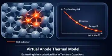
Discharge time characteristics for different discharge resistors.

3 Gorges dam, Hubei province

3 Gorges dam, Hubei Province, China. The hydro power station uses Metrosil exciter discharge varistors.

Advantages of Metrosils in Exciter Discharge Systems

Metrosil offers a high-speed solution to the discharge of excitation systems. This is due to the degree of non-linearity in the V-I characteristics of the discs.

In addition to providing short discharge times, Metrosil can also be employed in high energy applications, because the discs may be matched easily. This ‘matching’ describes how the difference in the electrical properties of the discs establishes the sharing of energy and current within a Metrosil.

If the discs are not matched appropriately in a unit, it may cause uneven current and energy distributions in the unit and limit the rating of the unit or probably lead to failure. Problems in matching with highly non-linear varistors limits their utilization to low energy applications.

Metrosil combines the energy absorption capability and the ideal characteristics of non-linearity for exciter discharge applications.

An unspaced Metrosil unit

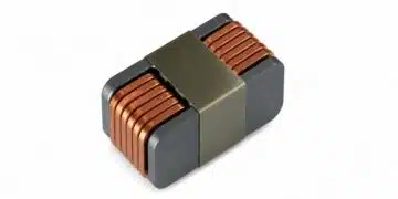
An unspaced Metrosil unit as used in a switched static exciter discharge system.

Customized Solutions

For medium to large exciter discharge applications, it is normal to switch in the exciter discharge system at the same time as switching out the supply voltage. This can be attained through a field breaker or a thyristor crowbar control system. This technique is widely employed in static excitation systems.

switched exciter discharge circuit

Typical arrangement of a switched exciter discharge circuit.

The user defines the following parameters of the system in order to develop a customized unit for an exciter discharge application:

  • Maximum discharge current from the field coil
  • Required protection voltage under discharge conditions
  • Energy stored in the field coil

Considerations for the protection voltage and energy to be dissipated must also be made regarding the three-phase short-circuit currents, which can be up to three times the level of the maximum discharge current.

A suitable unit may then be defined by the Metrosil engineers. Many units employ 150 mm diameter discs, which are coupled in series and parallel arrangements, based on the necessary electrical parameters. The number of discs and their thickness is dependent on the application details.

Metrosil exciter discharge units

Metrosil exciter discharge units arranged in parallel in a large hydro power system.

Alternative Exciter Discharge Systems

Customized units suitable for brushless and permanently connected exciter discharge systems – as employed on smaller synchronous generators – can be provided. A wider range of parameters should be considered in these applications, including:

  • The mechanical stability of the unit
  • Leakage current considerations
  • Power dissipation under normal operating conditions

Metrosils installed on a generator with a brushless excitation system

Metrosils installed on a generator with a brushless excitation system.

spaced Metrosil unit

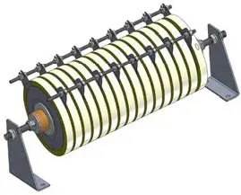
A spaced Metrosil unit as used in a permanently connected static exciter discharge system.

Metrosil unit

Large static excitation system showing Metrosil unit mounted from the cabinet ceiling.

Related

Recent Posts

Researchers Demonstrated High Energy Ceramic Capacitors Stable in Wide Temperature Range

2.10.2025
24

Stackpole Offers High Voltage Plate Resistors up to 40KV

2.10.2025
16

How to Manage Supercapacitors Leakage Current and Self Discharge 

1.10.2025
38

Experimental Evaluation of Wear Failures in SMD Inductors

1.10.2025
36

Resonant Capacitors in High-Power Resonant Circuits

1.10.2025
36

Littelfuse Releases First Reflow-Compatible Illuminated Tactile Switch

1.10.2025
7

Vishay Unveils 5W Power Metal Strip Resistor in Compact 1206 Case Size

1.10.2025
23

Components Thermal and Frequency Challenges in 6G Base Stations

30.9.2025
18

Layer-by-Layer Fabrication of Thin Polypropylene-based Dielectrics

30.9.2025
24

Reliability of E-Textile Conductive Paths and Passive Component Interfaces

29.9.2025
22

Upcoming Events

Oct 8
11:00 - 12:00 CEST

PCB Online Shop – simply “Made in Germany” by Würth Elektronik

Oct 14
16:00 - 17:00 CEST

Smart Sensors, Smarter AI: Building Reliable Edge Systems

Oct 17
12:00 - 14:00 EDT

External Visual Inspection per MIL-STD-883 TM 2009

Oct 20
October 20 - October 23

Digital WE Days 2025 – Virtual Conference

Oct 21
October 21 @ 12:00 - October 23 @ 14:15 EDT

Space and Military Standards for Hybrids and RF Microwave Modules

View Calendar

Popular Posts

  • Buck Converter Design and Calculation

    0 shares
    Share 0 Tweet 0
  • Boost Converter Design and Calculation

    0 shares
    Share 0 Tweet 0
  • Flyback Converter Design and Calculation

    0 shares
    Share 0 Tweet 0
  • LLC Resonant Converter Design and Calculation

    0 shares
    Share 0 Tweet 0
  • SEPIC Converter Design and Calculation

    0 shares
    Share 0 Tweet 0
  • Ripple Current and its Effects on the Performance of Capacitors

    3 shares
    Share 3 Tweet 0
  • What is a Dielectric Constant and DF of Plastic Materials?

    4 shares
    Share 4 Tweet 0
  • Dual Active Bridge (DAB) Topology Explained

    0 shares
    Share 0 Tweet 0
  • Flying Capacitors Explained

    0 shares
    Share 0 Tweet 0
  • MLCC and Ceramic Capacitors

    0 shares
    Share 0 Tweet 0

Newsletter Subscription


Passive Components Blog

© EPCI - Leading Passive Components Educational and Information Site

  • Home
  • Privacy Policy
  • EPCI Membership & Advertisement
  • About

No Result
View All Result
  • Home
  • Knowledge Blog
  • Premium Suppliers

© EPCI - Leading Passive Components Educational and Information Site

This website uses cookies. By continuing to use this website you are giving consent to cookies being used. Visit our Privacy and Cookie Policy.
Go to mobile version