


Knowles Precision Devices has expanded its ceramic core inductor portfolio to address a broader range of RF and microwave designs where stable inductance, predictable Q, and consistent manufacturability are critical.
The Knowles Precision Devices ceramic core RF inductor updated range targets standard commercial, industrial, telecom, and medical applications that need reliable RF signal conditioning without the cost and lead time penalties of highly specialized components.
By combining high‑Q factor ceramic cores with standard terminations and optional non‑magnetic variants, these inductors give RF designers and purchasing teams a practical balance of RF performance, availability, and cost for mainstream designs.
Key features and benefits
- Stable inductance over a broad RF range – The ceramic core construction is optimized for predictable inductance values across a wide frequency span typical of RF filters, impedance matching networks, and oscillators. This helps maintain tuned responses without repeated re‑tuning during validation.
- High Q and controlled self‑resonant frequency (SRF) – The portfolio is designed for reliable Q and SRF performance in standard RF applications, supporting good insertion loss, low phase distortion, and efficient power transfer in the intended operating band.
- Standard nickel barrier terminations – The default nickel barrier terminations support mainstream assembly processes, including solder reflow, while helping to control solder wetting and joint reliability in high‑volume production.
- Non‑magnetic copper termination options – For MRI and other magnetically sensitive designs, non‑magnetic copper terminations avoid ferromagnetic materials in the RF path, reducing distortion and interference in strong magnetic fields.
- Consistent manufacturability – The series is engineered as a portfolio rather than as isolated part numbers, helping to ensure tight process control and repeatable RF performance across different inductance values and lots.
- Cost‑effective for volume production – The range is positioned with competitive pricing and short lead times for high‑volume designs, making it suitable for cost‑sensitive industrial and telecom products as well as medical equipment where approved vendor lists and supply continuity matter.
- Broad application coverage – One family covers multiple segments (industrial, IoT, medical imaging, telecom, navigation), simplifying approved source management and reducing the number of different inductor families that purchasing needs to qualify and track.
Typical applications
Knowles ceramic core inductors target RF and microwave circuits where stability, availability and consistent RF characteristics are more important than pushing absolute performance limits.
RF and microwave signal conditioning
- Filters and matching networks in industrial RF front‑ends and IoT radios.
- Impedance matching between power amplifiers and antennas in telecom and broadband equipment.
- Oscillator and resonator networks where predictable inductance helps maintain frequency stability over temperature and production spread.
Medical and magnetically sensitive systems
- MRI RF coils and associated matching/filter networks, where non‑magnetic termination options help avoid field distortion and parasitic forces in high magnetic fields.
- Other medical RF subsystems that must avoid ferromagnetic materials near patients or sensitive measurements.
Industrial, telecom and navigation equipment
- Industrial and IoT systems that require robust, repeatable RF performance for long product lifetimes and field reliability.
- Telecom base stations, repeaters, and broadband access equipment needing predictable high‑Q inductors in LNAs, drivers, and filter stages.
- Navigation systems (for example, GNSS receivers or aviation navigation equipment) where stable inductance supports stringent sensitivity and selectivity requirements.
Technical highlights
Public details in the press information focus on the electrical behavior and termination options rather than specific catalogue values. For exact inductance ranges, tolerances, case sizes, and current ratings, designers should always refer to the manufacturer datasheet for the specific A‑Series ceramic core inductors.
Electrical characteristics
- Inductance range – Offered as a portfolio of ceramic core inductors covering common RF inductance values according to the manufacturer datasheet.
- Q factor and SRF – Designed for “high‑Q” behavior with controlled self‑resonant frequency, enabling use in narrowband filters, tuned matching networks, and oscillators where low loss and well‑defined resonance are required.
- Frequency range – Suitable for RF and microwave applications spanning typical industrial, telecom, and medical bands; designers should select part numbers with appropriate SRF and Q at the operating frequency per the datasheet.
Mechanical and termination options
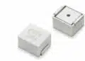
- Core and body – Ceramic core construction for mechanical stability and good dimensional control, which supports consistent inductance and automated assembly.
- Standard terminations – Nickel barrier terminations for compatibility with standard soldering processes (for example, Sn‑based lead‑free solders), supporting good adhesion and wetting behavior.
- Non‑magnetic terminations – Copper‑based non‑magnetic terminations for MRI and other magnetic‑field‑sensitive designs, helping to minimize distortion of static and RF magnetic fields.
Typical selection parameters
The following table summarizes the main selection parameters engineers will focus on when choosing from the portfolio (concrete values are according to the manufacturer datasheet):
| Parameter | What to check in datasheet | Practical implication in design |
|---|---|---|
| Inductance value | Nominal inductance and tolerance | Sets resonance/matching; tighter tolerance eases tuning |
| Q factor vs frequency | Q curves across operating band | Higher Q reduces filter loss and improves selectivity |
| Self‑resonant frequency (SRF) | SRF at specified test conditions | Operating frequency should remain well below SRF |
| Rated current / power | Maximum current and associated temperature rise | Determines suitability for power handling in RF path |
| DC resistance (DCR) | Typical and max DCR | Impacts insertion loss and efficiency |
| Case size / footprint | Dimensions and pad layout | Affects PCB density and layout constraints |
All of these parameters should be verified in the latest datasheet and simulation models before freezing the design.
Design‑in notes for engineers
Practical selection guidelines
- Start from operating frequency and SRF margin – Choose candidate part numbers with an SRF comfortably above the intended operating frequency to avoid unwanted parasitic resonance and degraded Q. A typical rule‑of‑thumb is to keep the operating frequency well below the listed SRF for that inductance value.
- Evaluate Q in the real band of interest – Check Q versus frequency data in the datasheet around the actual working band, not only at the nominal test frequency. For narrowband filters or matching networks, even modest Q variation can change insertion loss and bandwidth.
- Consider DCR and current handling – For inductors used in RF power paths (for example, PA output matching), verify that DCR and current rating are compatible with the expected RF currents, including modulation peaks and mismatch conditions.
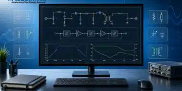
- Account for layout parasitics – Ceramic core inductors at RF and microwave frequencies are sensitive to pad geometry, ground proximity, and nearby conductors. Use the recommended land pattern and, where possible, EM simulation models from the manufacturer to capture parasitics.
Application‑specific considerations
- MRI and magnetically sensitive designs – For MRI coils and associated RF chains, select the non‑magnetic copper termination options to avoid signal distortion and mechanical forces in high static fields. Verify that all associated passives in the chain follow the same non‑magnetic material constraints.
- Industrial and IoT radios – For compact PCBs with dense RF front‑ends, the ceramic core construction and high‑Q performance support small filters and matching networks with good repeatability. Pay attention to part‑to‑part tolerance and lot variation when defining production test limits.
- Telecom and broadband systems – In base stations and broadband CPE, use the portfolio’s consistent manufacturability to standardize on a limited set of inductance values for LNA, mixer, and PA matching stages. This can simplify both design libraries and purchasing.
Reliability and qualification
- Derating and environment – While these inductors target standard commercial, industrial, medical, and telecom environments, engineers should apply normal derating guidelines for RF power, ambient temperature, and expected lifetime as defined in the datasheet and relevant internal standards.
- Change management – Because the family is available through distribution and targets high volume, keep an eye on PCN/PDN notices from Knowles to ensure that any process or material changes are captured in your component engineering workflow.
Source
This article is based on a manufacturer news post announcing the expansion of the Knowles ceramic core inductor portfolio for RF and microwave applications, complemented by information from the associated product literature and datasheet overview provided by Knowles.