








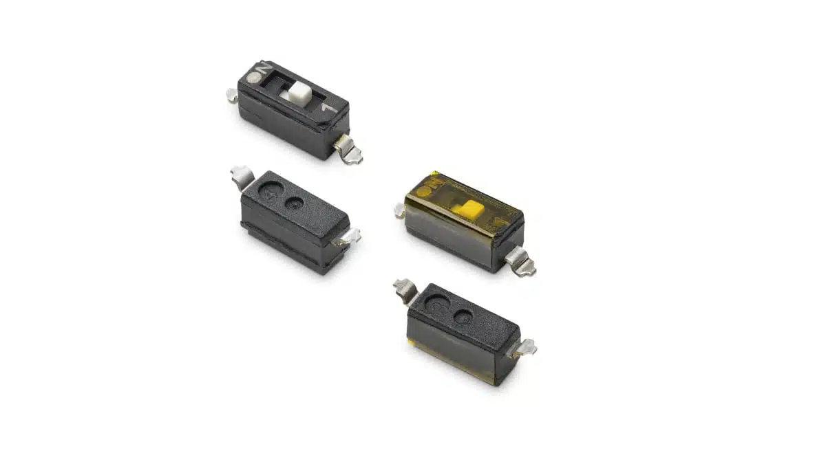
Littelfuse has introduced the C&K SDE series of end-stackable surface-mount DIP switches for low-power configuration circuits.
The Littelfuse DIP switches family combines a 0.1-inch switch-position pitch with flush or extended actuators and gull-wing terminals. Side-by-side stacking supports configurable switch banks, while top-tape-sealed versions support washable board processing.
Key features and benefits
- End-stackable construction supports adjacent switch packages on a standard 0.1-inch pitch.
- Position counts cover 1 through 10 and 12, with independent single-pole, single-throw contacts.
- Contact ratings distinguish 25 mA switching at 24 V DC from 100 mA non-switching duty.
- Copper-alloy contacts have gold plating over nickel; maximum contact resistance is 100 mΩ.
- Flush and extended actuators provide alternative mechanical arrangements for configuration access.
- Top-tape-sealed versions support washable processing. Versions without tape are also available.
- Tube and tape-and-reel packaging support different assembly flows.
- All plastics are UL 94 V-0 grade. The series is RoHS compliant and halogen-free.
Technical highlights
Electrical ratings and endurance
| Parameter | Value | Condition |
|---|---|---|
| Contact function | SPST | Independent positions |
| Position counts | 1–10 and 12 | Series options |
| Switching rating | 24 V DC, 25 mA | During actuation |
| Non-switching current | 100 mA | Static contact state |
| Contact resistance | 100 mΩ maximum | Closed contact |
| Insulation resistance | 100 MΩ minimum | At 100 V DC |
| Dielectric strength | 500 V DC minimum | 60 s |
| Mechanical life | 1,000 cycles | Actuation endurance |
| Electrical life | 1,000 cycles | Switching endurance |
| Moisture sensitivity level | MSL 1 | Assembly handling |
The switching and non-switching current ratings serve different duties. A contact carrying a static current within the 100 mA non-switching limit must still remain within the 25 mA switching limit when its position changes. This distinction matters where configuration settings can be adjusted while the board is powered.
The insulation-resistance and dielectric-strength values are test characteristics, not alternative working-voltage ratings. Circuit selection should use the 24 V DC contact rating rather than the dielectric withstand value.
The 1,000-cycle mechanical and electrical life makes expected adjustment frequency a selection factor. Installation and service settings should be assessed against the total number of changes anticipated over the equipment’s operating life.
Construction and assembly
The case and cover use PPS, and the actuator uses LCP. Both materials are UL 94 V-0 grade. Contacts use copper alloy with gold plating over nickel; the insert-moulded copper-alloy terminals have gold flash over nickel. The tape seal is polyimide.
The package uses a moulded 0.3-inch integrated-circuit packing outline for automatic insertion. Gull-wing terminations provide the surface-mount connection, and the soldering reference is IPC/JEDEC J-STD-020D.
Top-tape sealing is an ordering choice rather than a feature of every configuration. The sealing code is therefore important when washable processing forms part of the assembly route.
Package options and ordering
The ordering structure separates position count, actuator, termination, contact material, sealing and packaging.
| Ordering field | Code | Selection |
|---|---|---|
| Position count | SDE01–SDE10, SDE12 | 1–10 and 12 positions |
| Actuator | H0 / H1 | Flush / extended |
| Termination | S | Gull wing |
| Contact material | B | Gold |
| Sealing | Blank / D | Top tape / without tape |
| Packaging | Blank / R | Tubes / tape and reel |
For example, SDE04H0SBR is a four-position, flush-actuator version with gull-wing terminals, gold contacts, top-tape sealing and tape-and-reel packaging. SDE08H1SBDR is an eight-position version with an extended actuator, no tape seal and tape-and-reel packaging.
Body length increases with position count. Selected dimensions illustrate the space required along the switch bank:
| Configuration | Flush, tape-and-reel code | Body dimension A |
|---|---|---|
| 1 position | SDE01H0SBR | 2.50 ± 0.50 mm |
| 4 positions | SDE04H0SBR | 10.12 ± 0.50 mm |
| 8 positions | SDE08H0SBR | 20.28 ± 0.50 mm |
| 10 positions | SDE10H0SBR | 25.36 ± 0.50 mm |
| 12 positions | SDE12H0SBR | 30.43 ± 0.50 mm |
End stacking allows packages to form a longer bank, but additional positions still require board length and corresponding connections. A PCB intended to support different populated configurations should reserve the necessary land patterns and actuator access from the outset.
Typical applications and application fit
Target applications include industrial control equipment, garage door systems, security and fire systems, and IoT devices.
Within these systems, the 24 V DC, 25 mA switching rating supports low-power configuration duties. The independent SPST contacts and available position counts allow the switch bank to match the number of configuration settings required.
For industrial controls, the main selection points are contact voltage, current during adjustment and the required number of positions. Garage door, security and fire-system boards require the same separation between configuration switching and higher-current circuit functions.
In IoT devices, package length and actuator access must be considered together. A flush actuator changes the mechanical arrangement, while an extended actuator changes access requirements; neither option removes the need to accommodate the selected position count.
Design-in notes for engineers
- Check the electrical duty. Assess the voltage across an open contact and the current through a closed contact, including the conditions present when a setting changes.
- Separate switching from static current. Apply the 25 mA switching limit during actuation rather than treating the 100 mA non-switching rating as an interchangeable limit.
- Select the complete ordering code. Position count, actuator style, sealing and packaging must match the BOM and assembly route.
- Use the SDE land pattern. Check terminal geometry, package tolerances and adjacent-package spacing before layout release.
- Reserve actuator access. Account for neighbouring components, enclosure features and the intended adjustment method.
- Match sealing to cleaning. Choose the top-tape-sealed configuration where washable processing is required.
- Establish the assembly state. All switches are supplied in the OFF position; production programming and inspection should account for the required final settings.
- Assess adjustment frequency against the 1,000-cycle mechanical and electrical life.
- Validate final selection under the actual electrical, mechanical and assembly conditions before production release.
Tube and tape-and-reel packaging are available. Samples can be requested through authorised Littelfuse distributors.
Source
This article is based on the Littelfuse product announcement and official product documentation. Engineers should refer to the current manufacturer datasheet for final design and qualification.
References
- SDE Series: Low Profile End-Stackable Surface Mount DIP Switches, Littelfuse / C&K, revised July 21, 2026.