











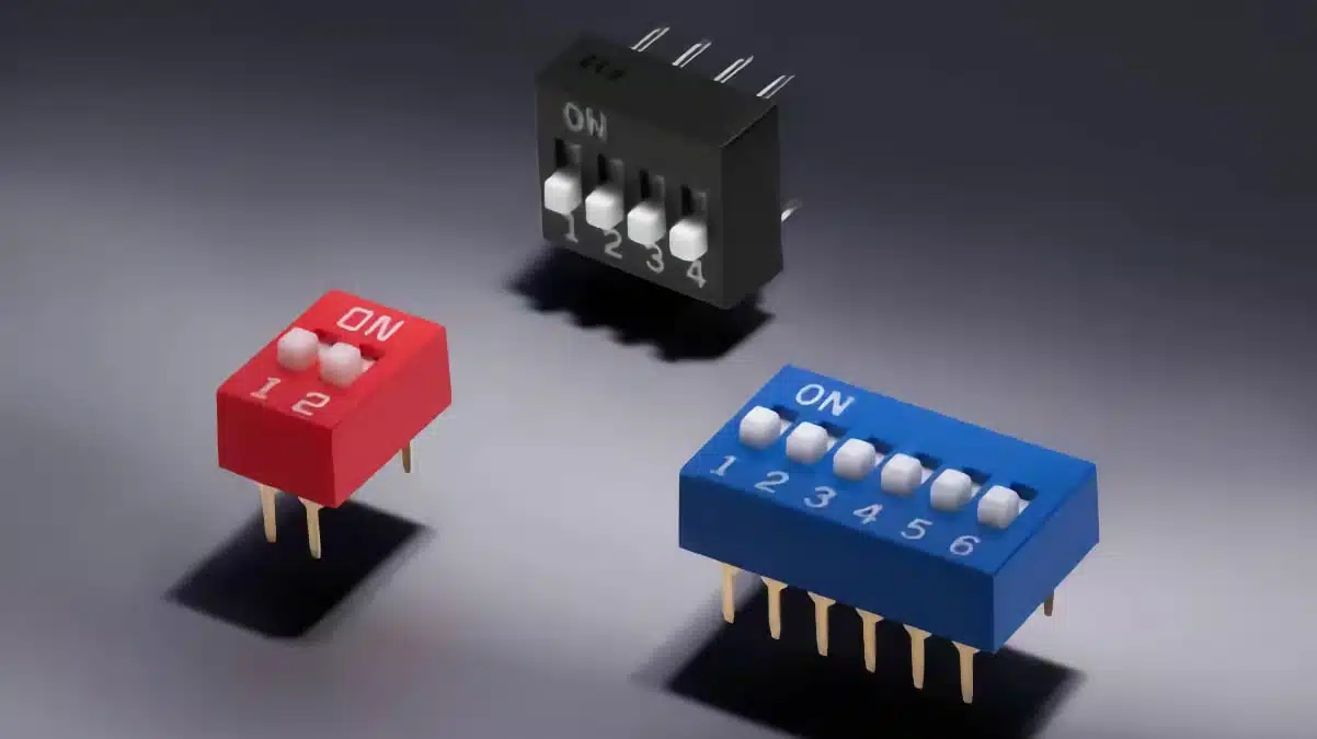
SCHURTER has introduced the DSTH series of standard-profile through-hole DIP switches with a 2.54 mm pitch.
The SCHURTER DIP switch series provides a simple hardware interface for setting addresses, communication parameters, logic states and operating modes without changing software or firmware.
The announcement is relevant where a product needs visible, serviceable local configuration on the PCB, including industrial controls, servers and equipment that must retain a defined hardware setting independently of firmware.
Key features and benefits
- 2.54 mm standard pitch: The DSTH uses the familiar DIP-switch pitch for conventional through-hole PCB layouts and manual configuration access.
- THT construction: Through-hole mounting can suit assemblies where mechanical retention, straightforward hand assembly or wave-solder processing are important.
- SPST switching elements: Each switch position provides an independent single-pole, single-throw contact for binary configuration inputs.
- Multiple position counts: SCHURTER lists 2 to 10, plus 12-position versions, allowing designers to match the number of available configuration bits to the required function.
- Extended actuator: The manufacturer states that the actuator is extended for easier manual operation.
- Finish and colour options: The product family is available with gold- or tin-plated terminals and contacts, and with black, red or blue housings according to the listed variants.
- Hardware-defined settings: A DIP switch can retain a physical configuration state during power-off conditions, avoiding the need for non-volatile memory when a fixed local setting is sufficient.
Technical highlights
| Parameter | Published value |
|---|---|
| Contact configuration | SPST |
| Contact positions | 2 to 10 and 12 |
| Pitch | 2.54 mm |
| Switching voltage, frequently changed state | 24 VDC |
| Switching current, frequently changed state | 25 mA |
| Switching voltage, constant state | 50 VDC |
| Switching current, constant state | 100 mA |
| Initial contact resistance | Maximum 50 mΩ |
| Contact resistance after testing | Maximum 100 mΩ |
| Dielectric strength | 500 V AC, 50/60 Hz, 1 minute |
| Mechanical lifetime | 2,000 actuations |
| Actuating force | Maximum 8 N |
| Operating and storage temperature | -40 °C to +85 °C |
| Soldering method | Wave soldering, up to two passes |
| Solderability condition | 260 °C maximum for 5 seconds |
The switching ratings are separated by use condition. The 25 mA at 24 VDC rating applies where the switch state changes frequently, while the 100 mA at 50 VDC rating applies to a constant switching state. Engineers should not treat these as interchangeable limits; the expected switching duty must match the manufacturer’s stated condition.
The published dielectric-strength value is a withstand test, not a normal operating-voltage rating for arbitrary circuits. Circuit-level working voltage, isolation requirements, pollution degree, creepage and clearance remain matters for the complete product design.
Application fit
SCHURTER identifies PLC controls, servers, medical devices, robotics, air-conditioning equipment and household appliances as application areas. The switches can be used for RS485 or Modbus address selection, BIOS/CMOS settings, and configuration of hardware functions or operating modes.
| System function | Practical use of DIP settings |
|---|---|
| RS485 or Modbus nodes | Sets a unique device address during installation or commissioning |
| PLC and industrial control boards | Selects operating mode, local options or hardware function states |
| Servers and embedded computing | Defines service, boot or board-level configuration settings |
| Medical and laboratory equipment | Enables controlled service configuration where physical access is required |
| HVAC and appliances | Selects product variants, operating modes or installed-option states |
For design engineers, this means the DSTH is suited to low-level configuration interfaces rather than power switching. The contact ratings should be checked against pull-up or pull-down currents, input protection networks, capacitive loading and any fault current that may reach the switch.
Design-in notes for engineers
- Confirm the exact variant: Select the required number of positions, housing colour, contact plating and ordering code from the current DSTH variant table before releasing the BOM.
- Separate static and dynamic duties: Use the applicable 24 VDC/25 mA or 50 VDC/100 mA limit according to whether the switch will be changed frequently or is intended to remain in a constant state.
- Check the input circuit: Verify the actual voltage and current at every switch position, including startup conditions, externally applied signals, ESD paths and fault conditions.
- Define the default logic: Pull-up or pull-down resistors should establish an unambiguous input level when the contact is open. Firmware should also define how invalid or changed switch combinations are handled.
- Allow physical access: Ensure the actuator remains accessible after enclosure assembly, and document ON/OFF orientation clearly on the silkscreen and in service documentation.
- Validate the PCB footprint: Use the manufacturer’s current symbol, footprint, 3D model and mechanical documentation for layout release. The announcement does not specify all dimensions; confirm them in the current datasheet.
- Qualify soldering: The stated process capability is wave soldering up to two times, with a maximum solderability condition of 260 °C for 5 seconds. Confirm compatibility with the actual assembly profile, PCB thickness, fixture arrangement and production process.
- Assess lifetime realistically: The listed 2,000-actuation mechanical lifetime may be sufficient for commissioning or service settings, but it should be reviewed carefully if operators will change settings repeatedly during normal use.
- Check the environmental margin: The stated operating range is -40 °C to +85 °C. Validate final enclosure temperature, contamination exposure, vibration and accessibility under the intended system conditions.
Further reading
- SCHURTER Releases Compact SMT DIP Switches
- How to Process Through-Hole Components by Reflow Assembly
Source
This article is based on the SCHURTER press release and current DSTH product documentation. Engineers should consult the current manufacturer datasheet, variant information and associated CAD data for final component qualification, PCB layout and production release.












