











High-power AI data-center racks are driving interest in higher-voltage DC distribution and compact isolated conversion stages.
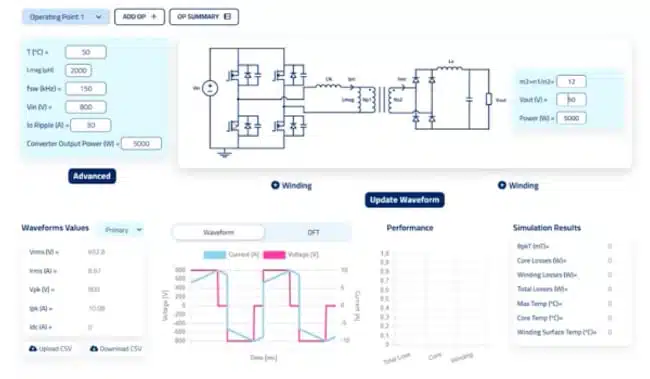
This design example article prepared based on Frenetic webinar examines the transformer and winding decisions behind a 5 kW, 800 V-to-50 V phase-shifted full-bridge (PSFB) converter, with particular attention to low-profile magnetic construction, copper loss, cooling, and soft-switching requirements.
Why this topic matters
The presentation uses an 800 V input and 50 V output as an illustrative intermediate conversion stage for high-density data-center power systems. At 5 kW, the nominal 50 V output current is 100 A, making transformer winding design, thermal removal, and secondary-side current distribution central constraints rather than secondary implementation details.
A rack installation also imposes a strong mechanical limitation: one magnetic dimension may be limited to approximately 30–40 mm. That constraint can rule out otherwise familiar E-core choices with insufficient effective core area and directs the design toward low-profile planar, EQ, or PQ-derived core geometries.
Operating principle
A PSFB converter uses phase shift between the bridge legs to regulate power transfer through an isolation transformer. The topology is suitable for high-power isolated DC/DC stages because it can support controlled switching transitions and because transformer leakage inductance can contribute to zero-voltage switching (ZVS).
The transformer turns ratio is selected not only to transform voltage, but also to preserve control margin. The presenter uses a nominal turns ratio of 12 in the example so the primary bridge retains phase-shift range to correct output voltage as operating conditions vary. A ratio of 16 was also noted as feasible, with the potential to increase primary turns and reduce core loss.
The video sets an illustrative switching frequency of 150 kHz and a 50 °C ambient temperature. These should not be read as universal requirements: the optimum switching frequency, flux-density limit, turns ratio, and thermal margin depend on semiconductor technology, core material, cooling arrangement, efficiency target, and allowable volume.
Magnetic constraints
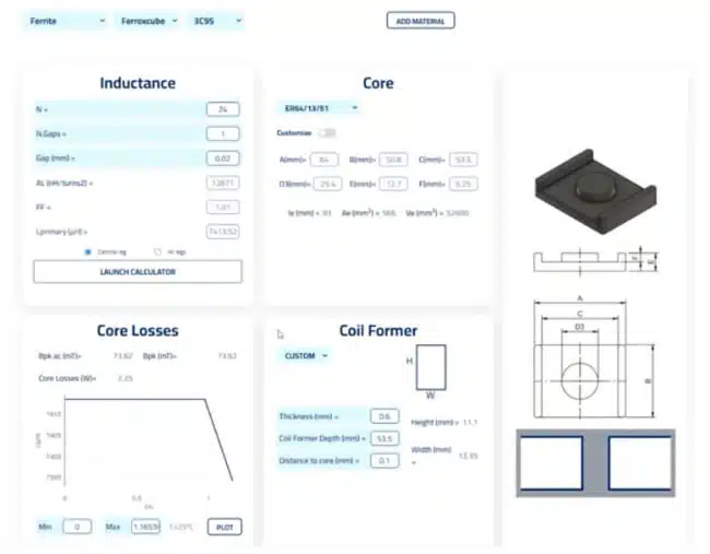
The transformer design begins with a flux-density limit of 150 mT to constrain core loss. With a 12:1 ratio, the available primary-turn choices are constrained to multiples compatible with the ratio, such as 12 or 24 turns.
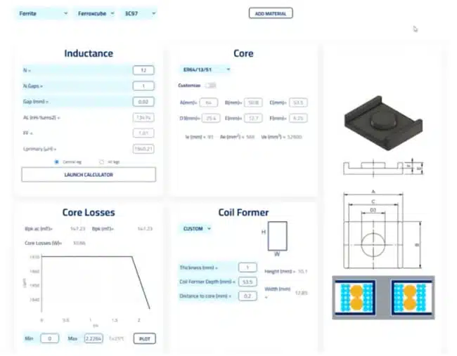
Increasing from 12 to 24 primary turns reduces the calculated core loss, but it also increases copper length and can raise winding loss. This is a core design trade-off: lower flux swing and core loss must be balanced against higher DCR, AC resistance, winding capacitance, manufacturing complexity, and available window area.
For a useful background on the interaction between material properties, frequency, and flux-density-dependent loss, see Core Magnetic Materials, Permeability and Their Losses.
Rectifier choice
The webinar compares secondary-side full-bridge rectification with centre-tapped rectification. A centre-tapped secondary can reduce the number of synchronous-rectifier MOSFETs from four to two, but the magnetic structure requires two secondary windings carrying substantial current.
| Design aspect | Full-bridge secondary rectification | Centre-tapped secondary rectification |
|---|---|---|
| Synchronous rectifier switches | Four | Two |
| Secondary winding arrangement | One secondary winding | Two secondary windings |
| Copper-window use | More favourable in the illustrated design | More constrained by two high-current secondaries |
| Magnetic outcome in the study | Lower winding-loss tendency | Higher winding losses in the comparable setup |
| Final decision | Depends on full converter optimisation | Depends on semiconductor and magnetic trade-offs |
With otherwise similar conditions, the presentation finds core-loss performance to be broadly comparable, while the centre-tapped configuration creates higher winding losses because the available winding space is more restricted. The presenter therefore considers the full-bridge option generally preferable from the magnetic-design perspective, while noting that either topology can be made to work.
Conventional winding study
The conventional low-profile transformer study uses a planar ER64-class core and an interleaved winding arrangement. In one trial, total transformer loss is approximately 30 W, against a stated target below 30 W and a preferred objective of roughly 25 W, corresponding to about 0.5% of the 5 kW power level.
The reported temperature in that initial case is approximately 176 °C, which is not acceptable as a practical result without reconsidering the thermal boundary conditions and component limits. Introducing assumed rack airflow of roughly 1–2 m/s reduces the calculated temperature and also changes loss estimates because resistance varies with temperature.
Cooling must therefore be treated as a design input, not an afterthought. The relevant boundary condition includes airflow direction and velocity, mounting location, thermal interfaces, nearby heat sources, enclosure restrictions, and the real cooling architecture—fan, heatsink, cold plate, or liquid cooling.
Planar winding option
For a profile-constrained magnetic design, the presentation evaluates PCB-based planar windings and a copper-stamp secondary. The example uses three four-layer PCBs with four primary turns each, while the secondary is implemented as a 0.5 mm copper stamp rather than consuming PCB layers.
The presenter targets a primary current density of approximately 10 A/mm² in the illustrated arrangement. However, average current density alone is not enough to qualify a high-frequency winding: skin and proximity effects can concentrate current unevenly, substantially increasing AC copper loss.
Skin and proximity losses in transformer windings become especially important as switching frequency rises and as conductors sit in strong magnetic fields. In the simulation shown, the planar arrangement provides a more favourable current-density distribution and lower winding loss than the compared litz-wire configuration.
Thermal and loss results
The video presents several iterative outcomes rather than a final universally optimised design. Their value is in showing how turns, winding geometry, cooling, and core size interact.
| Illustrative case from the video | Reported outcome | Editorial interpretation |
|---|---|---|
| Conventional winding trial | About 30 W transformer loss; temperature around 176 °C | Loss target may be approached, but the reported thermal result requires stronger cooling or a different design |
| Planar iteration with 24 turns | About 12 W loss; temperature around 130 °C | Lower loss does not automatically mean the lowest temperature because heat removal differs by winding construction |
| Custom planar ER72 iteration | About 10.2 W loss; peak temperature around 91.5 °C | A larger custom core can improve the loss-temperature balance within the studied model |
The presenter notes that transformer core losses are lowest in the approximate 60–100 °C range for the model and material conditions used. Engineers should verify this behaviour against the selected core manufacturer’s loss data and their actual frequency, flux density, temperature, tolerance, cooling, and production conditions.
Leakage inductance and ZVS
Reducing leakage inductance is often a desirable transformer objective because it can reduce voltage overshoot and circulating energy. In a PSFB converter, however, leakage inductance can also be deliberately used to support ZVS during bridge commutation.
This creates an important design nuance: the lowest possible leakage inductance is not necessarily the best result. The target value must be coordinated with switching devices, dead time, current range, clamp or snubber strategy, resonant transitions, transformer capacitance, and the required ZVS operating range.
A small air gap is proposed in the planar example to reduce primary inductance and address a self-resonant-frequency issue identified in the simulation. Any such gap must be assessed carefully because it can introduce fringing flux and additional winding loss. Planar transformer design practices are particularly useful when balancing low profile, interleaving, parasitic capacitance, and high-frequency copper loss.
Design-in notes for engineers
- Establish the complete electrical envelope: input-voltage range, output-voltage regulation range, output-current profile, switching frequency, overload duration, and expected control margin.
- Define the mechanical envelope before selecting a core; a nominal rack-height limit can eliminate many standard core geometries.
- Evaluate at least two turn-count options when ratio constraints restrict the design space; more turns may reduce core loss while increasing copper loss.
- Treat the transformer loss budget and thermal limit as separate constraints; an acceptable wattage result can still produce an unacceptable hot spot.
- Model DC and AC winding losses separately, including current harmonics, skin effect, proximity effect, conductor thickness, strand diameter, interleaving, and parallel-path current sharing.
- Validate whether parallel conductors actually share current; a simulated current-density map can reveal copper that adds little effective conduction area.
- Set a deliberate leakage-inductance target for PSFB ZVS rather than simply minimising it.
- Check self-resonant frequency, interwinding capacitance, common-mode EMI implications, insulation coordination, creepage, clearance, and partial-discharge risk in the 800 V environment.
- Measure prototype temperatures at core, primary winding, secondary winding, terminals, PCB copper, and local cooling interfaces under worst-case electrical and airflow conditions.
- Include capacitor stress in the complete converter validation; the presentation notes that capacitor analysis is available separately and was not fully demonstrated live.
Limits and trade-offs
Planar construction can improve profile, repeatability, copper utilisation, and integration with cooling hardware. It can also introduce practical constraints: multilayer PCB cost, layer-count limits, conductor-thickness limitations, parasitic capacitance, high-frequency AC loss, and more complex interconnection to high-current secondary structures.
The presentation proposes a hybrid approach as another option: litz wire on the primary and a copper stamp or PCB winding on the secondary. This may be particularly relevant where a gap near a PCB primary winding would expose the copper to fringing field.
The webinar also comments that resonant LLC converters can offer lower loss when operating at resonance, but it does not provide a direct, equivalent 5 kW PSFB-versus-LLC comparison. Its caution is important: the gap required to obtain the desired magnetising inductance in an LLC transformer can make a PCB primary winding vulnerable to fringing-field loss, which is one reason to consider hybrid windings.
Conclusion
The 5 kW, 800 V-to-50 V PSFB example demonstrates that compact data-center magnetics require simultaneous optimisation of core geometry, turns count, winding technology, leakage inductance, and cooling. In the presented simulations, a custom larger planar core and planar or hybrid winding concepts offer a better path to low profile and lower loss than the initial conventional-winding case.
The numerical outcomes are illustrative simulation results, not release-ready component specifications. A production design should be confirmed using material-characterisation data, tolerance analysis, high-frequency loss modelling, thermal measurements, EMI testing, insulation verification, and full-converter ZVS validation.
Further reading
- Planar vs Conventional Transformer: When it Make Sense
- Advanced Loss Modeling for Planar Magnetics
- Transformer Optimal Operating Frequency for PSFB Converter
- 1kW Phase Shift Full Bridge Converter Design and Simulation
Source
This article adapts the design workflow and illustrative simulation results presented by Frenetic for a 5 kW, 800 V-to-50 V PSFB converter intended for next-generation data-center applications.
References
- Frenetic: Designing a 5 kW, 800 V to 50 V PSFB Converter for Next Generation Data Centers
- Passive Components Blog event page: Designing a 5 kW, 800 V-to-50 V PSFB Converter for Next Generation Data Centers












