


Simulation tools such as REDEXPERT and eDesignSuite are increasingly central to modern power converter design workflows, because they let engineers validate magnetics and power stages long before hardware exists. Based on a discussion between Würth Elektronik and STMicroelectronics, this article outlines how these tools support inductor selection, loss analysis and efficiency optimization in practical designs, and why that matters for both design engineers and purchasing teams.
Key features and benefits
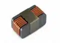
REDEXPERT is Würth Elektronik’s cloud‑based simulation platform focused on passive components such as power inductors, EMC components and other magnetics, with models that are derived from extensive lab measurements under realistic operating conditions.
The tool allows engineers to evaluate AC and DC losses, temperature rise and efficiency impact for specific Würth inductors in typical converter topologies, rather than relying only on catalogue values at a single operating point. eDesignSuite from STMicroelectronics complements this by offering reference designs and application schematics around ST controllers and power devices, where inductors and other passives can be selected and checked in context. Together, the two tools reduce trial‑and‑error hardware iterations and enable more confident design decisions earlier in the project lifecycle.
From a workflow standpoint, REDEXPERT integrates parametric search and performance comparison for Würth inductors, while eDesignSuite provides ready‑made ST evaluation boards and design examples that can be adapted to specific requirements. This combination makes it easier to start from a known good design, adjust key parameters such as output power or switching frequency, and immediately see how different inductors affect efficiency and thermal behaviour. For purchasing teams, the fact that these tools are tied to real components and measured data improves communication with engineering, because selected part numbers can be justified by simulated performance rather than only unit price or generic data sheet curves.
Typical applications
The tools and workflows described in the video are aimed primarily at switched‑mode power supplies, including buck converters and other common topologies used in industrial, automotive and consumer systems. Typical design tasks include sizing the output inductor for a DC‑DC converter on an ST evaluation board, checking ripple and saturation margins, and comparing several Würth inductor series for the same electrical specification. These scenarios occur in applications ranging from embedded controllers and sensor nodes up to multi‑hundred‑watt power stages, so the ability to quickly explore inductor options is relevant across many market segments.
Beyond simple single‑output converters, simulation‑aided inductor selection is also valuable in more complex topologies where magnetics strongly influence overall performance, such as multi‑phase buck converters or converters with tight efficiency and thermal limits. In such cases, using REDEXPERT to estimate losses in high‑current inductors, and eDesignSuite to validate the system‑level behaviour of the ST controller and MOSFETs, helps ensure the magnetics and semiconductors are matched appropriately. According to the discussion, this approach can reduce debugging time on the lab bench because potential problem areas such as excessive temperature rise or poor efficiency are visible in advance.
Technical highlights
A central technical focus in the video is the role of AC losses in inductors and how they impact efficiency, especially at higher switching frequencies and in designs that push ripple current or flux density.
REDEXPERT provides loss models that consider both DC resistance and frequency‑dependent effects, enabling engineers to estimate total inductor losses over the intended operating range instead of treating them as a simple problem. This is important because core losses and skin/strand effects can become significant under certain conditions, and they directly translate into temperature rise.
Temperature rise in an inductor affects not only component reliability but also nearby semiconductors and PCB layout constraints. By using the tool to compare several inductors with similar inductance and current rating but different core materials or geometries, engineers can see how each option behaves thermally and choose a device that fits both electrical and mechanical requirements. eDesignSuite’s role here is to give a realistic converter environment, including controller settings, switching frequency and load profile, so that inductor losses and temperatures are evaluated with representative waveforms rather than idealized assumptions.
Example parameter comparison
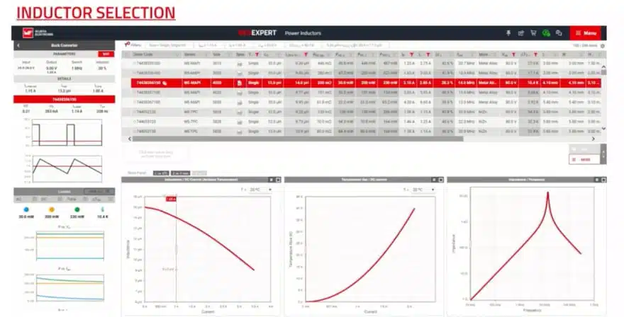
The workflow shown in the video illustrates how an engineer might start with the inductor parameters recommended for an ST evaluation board and then explore alternatives to fine‑tune efficiency or size. Within REDEXPERT, several Würth inductors can be selected and plotted on the same graph for losses or temperature rise at the operating point defined by the converter design. If a more compact inductor shows higher losses or a larger temperature rise than a physically larger alternative, the trade‑off between PCB space and thermal margin becomes clear.
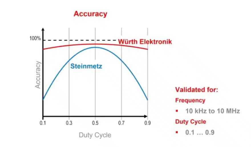
This type of analysis is also useful for understanding what “according to manufacturer datasheet” means in practice, because the measured‑based models in REDEXPERT extend beyond static catalogue values. Engineers still rely on data sheets for absolute maximum ratings and basic parameters, but the simulation adds insight into how close the design operates to those limits under realistic conditions. For purchasers, this can translate into better decisions when considering alternative inductors with similar headline specifications but different cost, availability or form factor.
Design‑in notes for engineers
The discussion repeatedly emphasizes that good inductor selection starts with a clear definition of boundary conditions: output power, input voltage range, switching frequency, ripple constraints and ambient temperature. Once these are known, eDesignSuite can be used to configure the ST controller and topology, and REDEXPERT can then be applied to test candidate inductors under those conditions. In practice, engineers should treat the simulation as a way to narrow down options to a short list that is then validated on hardware, rather than a replacement for measurement.
Another practical design‑in note is to consider how changes in operating point, such as higher load or different switching frequency, affect the selected inductor. REDEXPERT enables quick sweeps of current or frequency to show how losses and temperature rise evolve, so engineers can judge whether there is sufficient margin for worst‑case operation or future design changes. When designing for systems that might later be upgraded or reused, such foresight can prevent the need to requalify magnetics. The video suggests using these tools iteratively while refining the design, instead of only at the end of the process.
Workflow integration with evaluation boards
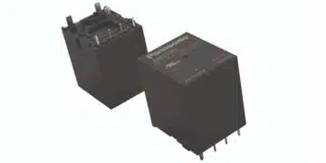
The STEVAL‑3601CV1 evaluation board from STMicroelectronics, which is mentioned in the video, serves as an example of how to bridge reference designs and component selection tools. Engineers can start with the board’s standard configuration, including its recommended inductor, and then use REDEXPERT to simulate alternative Würth inductors that might offer better efficiency or thermal behaviour. eDesignSuite provides the schematic and configuration framework, ensuring the system context remains accurate while components are varied.
By integrating such evaluation boards into the simulation workflow, teams can shorten the path from concept to prototype. Instead of redesigning the entire power stage from scratch, they can leverage ST’s design examples and Würth’s component models to customise the solution just enough to meet their specific requirements. This approach also helps purchasing because the final selected components are tied to proven reference designs and documented simulation results, making internal justification and communication more straightforward.
Conclusion
Engineers working on modern power converters face increasing pressure to deliver efficient, thermally robust solutions without extended lab iterations, and the combination of REDEXPERT and eDesignSuite directly targets this challenge.
By providing realistic inductor loss and temperature models, along with system‑level converter simulations and evaluation boards, these tools enable more informed magnetics selection and faster convergence on suitable designs. After understanding this workflow, designers should be able to use Würth’s and ST’s platforms to evaluate inductor options, anticipate efficiency impacts, and reduce debugging time, while purchasing teams gain better insight into the technical rationale behind chosen part numbers.
Source
This article is based on the technical discussion in the Würth Elektronik Watts Up podcast episode “Power Design Tools for Faster Simulation and Rapid Results,” featuring Würth Elektronik and STMicroelectronics, and reflects information presented there according to manufacturer documentation.
References
- Power Design Tools for Faster Simulation and Rapid Results – Würth Elektronik Group (YouTube video)[youtube]
- Würth Elektronik REDEXPERT online simulation platform[youtube]
- STMicroelectronics eDesignSuite design tool overview[youtube]
- STMicroelectronics STEVAL‑3601CV1 evaluation board information[youtube]