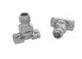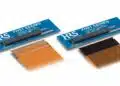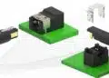
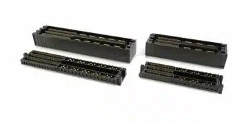






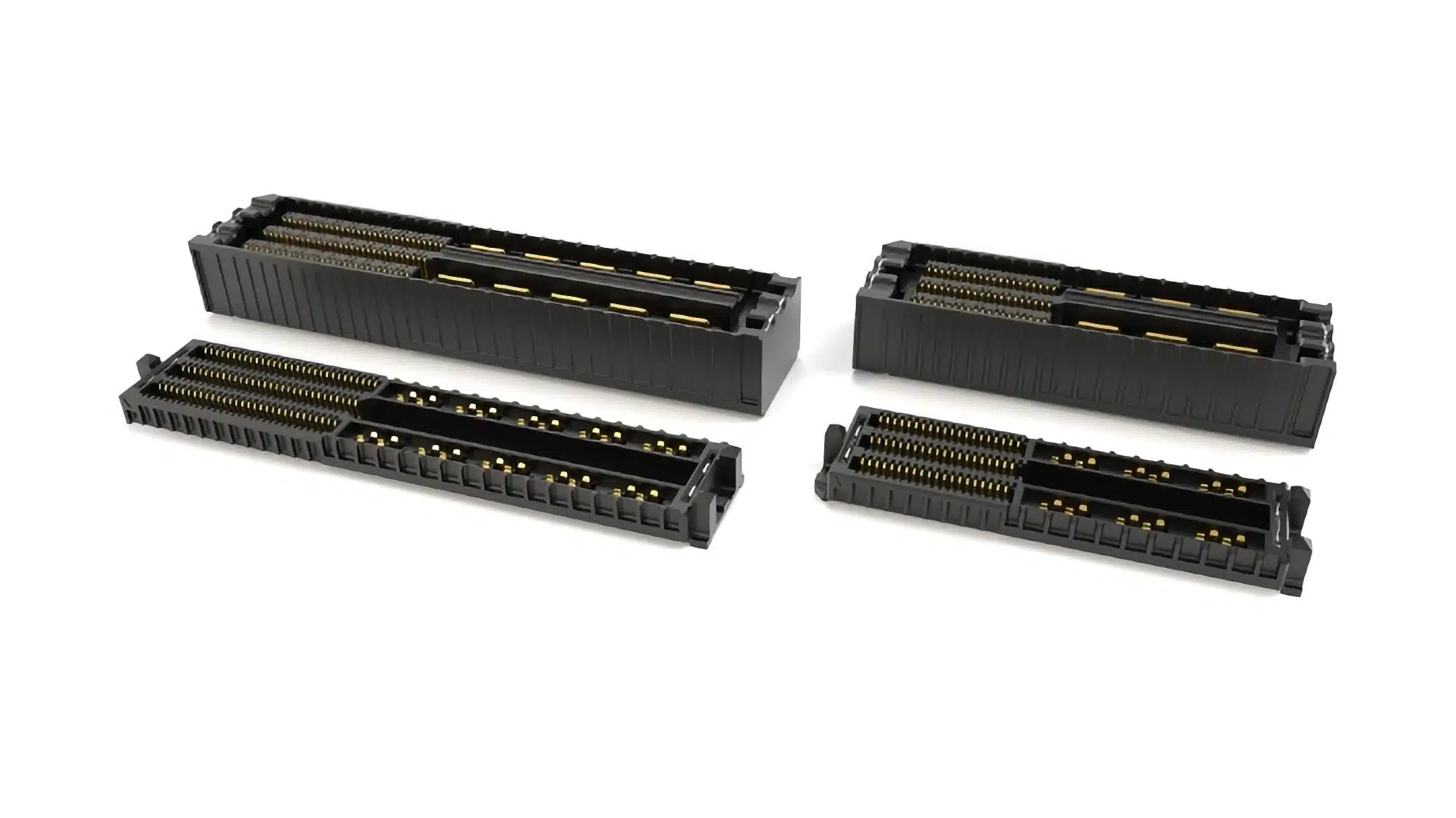
Samtec has introduced 10 mm stack-height AcceleRate mP board-to-board connectors, combining digital signal contacts and power blades in the UDM6 terminal and UDF6 socket series.
The interface brings a 0.635 mm-pitch signal array and power connections rated up to 15 A per blade into one connector pair, allowing signal and power routing without separate connectors.
Key features and benefits
- Integration: One mating interface combines an open-pin-field signal array with dedicated power blades.
- Signal density: A six-row array provides 60, 120, 180 or 240 signal positions on a 0.635 mm pitch.
- Power configurations: Options comprise 4, 6, 8 or 10 total power blades, arranged in two rows.
- Electrical capability: Power-blade ratings reach 15 A per blade and 200 V AC or 283 V DC.
- Signalling capability: The connector family supports 64 Gbps PAM4 and 32 Gbps NRZ applications, including PCIe 6.0 and CXL 3.2.
- Mechanical options: The family includes 5 mm and 10 mm mating stack heights, optional alignment pins, standard weld tabs and polarised guide posts for blind mating.
Technical highlights
Separate contact structures for signals and power
The UDM6 terminal mates with the UDF6 socket. Signal contacts occupy an open pin field, while dedicated blades carry power. The power blades run parallel to the connector body length, with a 90° rotation relative to common power-blade arrangements.
This orientation gives the blades access to heat escape paths and leaves space around the power connections for PCB breakout routing. The signal field remains configurable for single-ended signals, differential pairs, grounds and lower-speed power connections.
| Parameter | Value | Configuration |
|---|---|---|
| Terminal series | UDM6 | Mates with UDF6 |
| Socket series | UDF6 | Mates with UDM6 |
| Mating stack heights | 5 mm or 10 mm | Board-to-board |
| Signal-contact pitch | 0.635 mm | Six rows |
| Total signal positions | 60 / 120 / 180 / 240 | Configurable pin field |
| Total power blades | 4 / 6 / 8 / 10 | Two rows |
| Maximum blade current | 15 A per blade | Power contacts |
| Maximum voltage | 200 V AC / 283 V DC | Power rating |
| Signalling capability | 64 Gbps PAM4 | 32 Gbps NRZ |
Signal-contact allocation governs channel performance
The open-pin-field arrangement allows signal and ground assignments to follow the interface requirements rather than a fixed differential-pair pattern. Ground contacts can be placed to control impedance and reduce crosstalk. Planning these signal return paths through board-to-board connectors is therefore part of the pin-assignment task, not a separate layout detail.
The total signal-position count includes the contacts allocated to grounds and other functions; it is not a count of differential data lanes.
The 64 Gbps PAM4 and 32 Gbps NRZ capability uses a channel-based performance assessment that includes crosstalk and reflections. Achieving that performance requires suitable PCB design and the recommended connector breakout region. PCIe 6.0 and CXL 3.2 capability should therefore be assessed within the complete board-to-board channel, including both PCB transitions.
Typical applications
Target applications include:
- Datacom equipment.
- 5G and 6G wireless networks.
- Industrial automation and robotics.
- Military and aerospace systems.
- Instrumentation.
In datacom interfaces using PCIe 6.0 or CXL 3.2, the 64 Gbps PAM4 capability supports the high-speed signal requirement, while the dedicated blades provide a separate power path within the same mating interface.
For systems combining differential links, single-ended control signals and power, the configurable signal field allows the contact assignment to follow the system architecture. The choice of 5 mm or 10 mm mating height also allows the electrical interface to be coordinated with board spacing.
Design-in notes for engineers
- Choose the mating geometry first. Coordinate the UDM6 terminal and UDF6 socket with the required stack height, signal-position count and power-blade count.
- Allocate grounds alongside signals. Establish differential pairs, single-ended paths and return contacts before fixing the connector footprint and PCB breakout.
- Assess the complete signal channel. Include the connector pair, PCB launches, crosstalk and reflections when evaluating the required data rate.
- Evaluate power loading and heat escape together. Use the 15 A-per-blade maximum within the thermal assessment of the selected configuration and operating environment.
- Include mechanical features in the layout. Allow for alignment pins, weld tabs and polarised guide posts where used.
- Validate the selected mating pair, pin assignment, PCB breakout and power loading under actual operating conditions before production release.
Further reading
- Samtec Expands Offering of Slim, High-Density HD Array Connectors
- Samtec AcceleRate Slim ARC6 Cable Assemblies with New Signaling Options
Source
This article is based on the Samtec product announcement and official product documentation. Engineers should refer to the current manufacturer datasheet for final design and qualification.