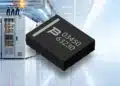







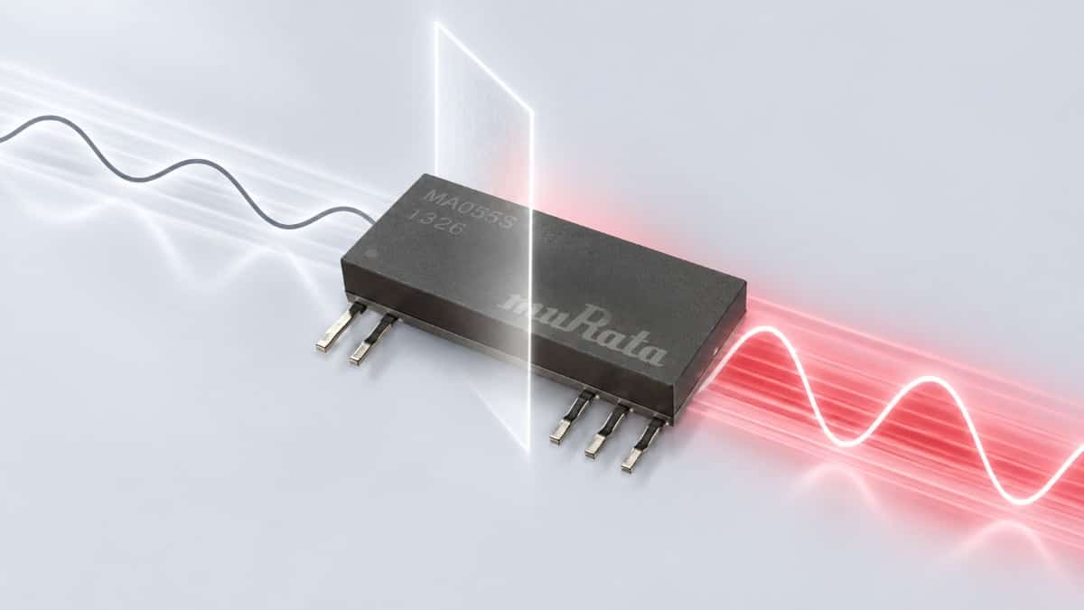
Murata has introduced the MGJ2T2 series of 2 W isolated DC-DC converters for high-voltage silicon carbide (SiC) gate-drive circuits.
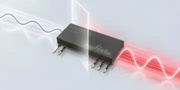
The Murata SIP modules convert a 24 V input into +18 V/−3 V bipolar outputs, combining gate-driver power with an isolation barrier rated for 6 kV DC withstand testing. Isolation capacitance of 2.5 pF and common-mode transient immunity exceeding 200 kV/µs address noise coupling in fast-switching power stages.
Key features and benefits
- Bipolar +18 V/−3 V outputs provide separate positive turn-on and negative turn-off supply rails for SiC MOSFET gate drivers.
- A 2 W output-power rating defines the available gate-drive power budget.
- Isolation capacitance of 2.5 pF limits capacitive coupling between the switching power stage and control-side circuitry.
- Common-mode transient immunity above 200 kV/µs supports operation during rapid changes in voltage across the isolation barrier.
- Working-voltage capability reaches 800 V RMS with reinforced insulation or 1600 V RMS with basic insulation.
- Creepage and clearance both exceed 8 mm.
- The operating temperature range spans −40 °C to +125 °C.
Technical highlights
| Parameter | Value | Notes |
|---|---|---|
| Output power | 2 W | Gate-drive supply |
| Input voltage | 24 V | DC input |
| Output voltages | +18 V/−3 V | Bipolar rails |
| Isolation withstand | 6 kV DC | Barrier test voltage |
| Isolation capacitance | 2.5 pF | Primary to secondary |
| CMTI | >200 kV/µs | Common-mode transients |
| Reinforced working voltage | Up to 800 V RMS | Reinforced insulation |
| Basic working voltage | Up to 1600 V RMS | Basic insulation |
| Creepage and clearance | >8 mm | Both distances |
| Operating temperature | −40 °C to +125 °C | Module operating range |
| Package | SIP | Single in-line package |
| Insulation design standard | IEC 60664-1 | Insulation coordination |
Isolation construction and switching noise
The MGJ2T2 series uses Block-Coil transformer technology. Separate windings are formed on solid insulating formers, physically separating the primary and secondary circuits while controlling the capacitance between them.
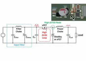
In an isolated gate-drive supply, the transformer barrier also creates a capacitive path for switching noise. Rapid voltage transitions drive displacement current through this capacitance and into the surrounding circuit. The 2.5 pF barrier capacitance addresses this coupling path, while the CMTI rating addresses tolerance of rapid common-mode voltage transitions. These are related but distinct selection parameters.
The 6 kV DC withstand rating is a barrier test voltage, not a continuous working-voltage rating. Insulation selection instead depends on the required protection level and the corresponding 800 V RMS reinforced or 1600 V RMS basic working-voltage capability.
Bipolar rails and the gate-drive power budget
The +18 V rail supplies the positive gate-drive voltage, while the −3 V rail supports turn-off. Negative gate bias helps counter unintended turn-on caused by current through the MOSFET’s Miller capacitance.
The 2 W rating must cover gate charging and discharging at the intended switching frequency, together with driver consumption and other secondary-side loads. It does not define the driver’s peak source or sink current. Local supply capacitors deliver the short current pulses associated with switching; their capacitance, ESR and ESL influence supply-rail droop.
Gate-drive resistor power losses also belong in the circuit assessment because the gate resistances dissipate energy during charging and discharging.
Typical applications
Target applications include energy storage systems, battery energy storage systems, microgrids, motor drives, industrial automation, EV charging and heat pumps.
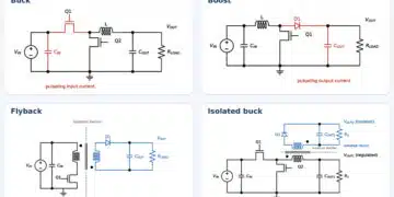
In these systems, the MGJ2T2 occupies the isolated auxiliary-supply position feeding a SiC gate driver. Its +18 V/−3 V rails establish the gate-bias supplies, while its working-voltage and transient-immunity ratings govern separation between the control electronics and switching stage.
Solid-state transformer architectures are another target. Cascaded switching stages can operate at different electrical potentials, making individual isolated gate-drive supplies relevant. The MGJ2T2’s insulation capability, 2.5 pF coupling capacitance and CMTI above 200 kV/µs address the isolation and switching-noise requirements of that circuit position.
Design-in notes for engineers
- Match both output rails to the selected SiC MOSFET’s gate-voltage limits and the gate driver’s supply requirements.
- Assess gate charge, switching frequency, driver consumption and auxiliary loads against the 2 W power budget.
- Select local rail capacitors for switching-pulse current, acceptable voltage droop, ESR and ESL. Keep the driver and supply connections close to the power switch.
- Evaluate loading on both output rails, including protection circuitry that may introduce unequal secondary-side currents.
- Treat insulation coordination separately from withstand testing. Include working voltage, protection level, pollution degree, overvoltage category, altitude and PCB spacing in the system assessment.
- Check supply-rail behaviour during start-up, shutdown and switching inactivity before enabling PWM operation.
- Validate the complete gate-drive assembly under its actual electrical and thermal operating conditions before production release.
Further reading
- Würth Enhances Transformers for SiC MOSFET Gate Drivers with Ultra Low Interwinding Capacitance
- Coilcraft Releases LLC Half-Bridge Transformers for Isolated Gate Driver Bias Supply
Source
This article is based on the Murata product announcement and official product documentation. Engineers should refer to the current manufacturer datasheet for final design and qualification.
References
- Murata Introduces New Series of Isolated DC-DC Converters for High-Voltage SiC Gate Drives, Murata Manufacturing Co., Ltd., 16 November 2026.
- Gate Drive Application Notes: IGBT/MOSFET/SiC/GaN gate drive DC-DC converters, Murata Power Solutions, 2018.