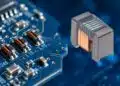

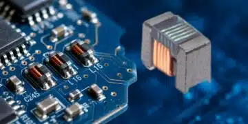


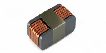


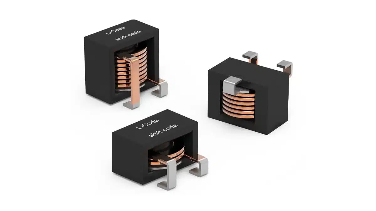
Würth Elektronik has introduced the WE-SFIA series of SMT flat-wire inductors in compact 2010, 2013, and 2016 packages aimed at high-efficiency power conversion in automotive electronics.
The combination of Würth Elektronik flat-wire winding technology, optimized core material, and an extended operating temperature range down to minus 40 degrees and up to 180 degrees Celsius targets demanding DC/DC converter and filter choke designs in space-constrained ECUs and power modules.
Key features and benefits
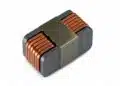
- Flat-wire winding for low losses: Flat conductors provide a larger cross-section than comparable round wire in the same winding window, which reduces direct current resistance and increases current-carrying capability for a given footprint.
- Very low DC resistance (DCR): The series is optimized for minimal copper losses, helping designers reach higher converter efficiency and reduce self-heating at high continuous currents.
- High saturation currents up to 150 A: The core and winding design support large transient and continuous currents, which is important for modern multiphase buck and boost stages in 12 V, 24 V and higher voltage automotive systems.
- Extended temperature range from -40 °C to +180 °C: The wide operating range supports under-hood, powertrain and other harsh automotive environments where ambient and hot-spot temperatures are significantly above standard industrial conditions.
- Compact SMT 2010, 2013, 2016 packages: Standardized surface-mount outlines simplify PCB layout and allow tight placement around controllers and MOSFETs in power stages.
- Improved magnetic saturation behavior: The optimized core material is designed to maintain inductance and avoid early saturation under high peak currents, which reduces the risk of increased ripple and switching losses in converters.
- Lower AC losses at high frequency: By using flat conductors and suitable core material, the series addresses skin and proximity effects in the hundreds of kilohertz range typical for modern DC/DC controllers.
- Catalog and customizable variants: Standard inductance values between 0.33 microhenry and 4.7 microhenry are available as off-the-shelf parts, with additional values and mechanical variants possible on request for platform designs.
Typical applications
The WE-SFIA power inductor series is positioned primarily for high-efficiency power stages in automotive electronics, but the underlying technology also fits a broader range of power and filter applications.
- Single-phase and multiphase step-down buck converters in 12 V and 48 V automotive power rails for ECUs, ADAS, infotainment, and body electronics.
- Step-up boost converters and combined buck-boost stages used in LED lighting, audio amplifiers, or power amplifiers where efficiency and thermal performance are critical.
- Battery management systems, including high-current DC/DC converters that interface between battery modules, auxiliary 12 V rails, or on-board chargers.
- Motor drive inverters and servo controllers in auxiliary electric drives, where compact power inductors are required for current smoothing and EMI control.
- Automotive audio and infotainment systems that require low-noise power rails and compact power stages near the load.
In many of these use cases, the extended operating temperature and high saturation current capability allow engineers to trade off between footprint, efficiency, and thermal headroom, rather than oversizing cores or heat sinks.
Technical highlights
The press material focuses on the electrical and thermal behavior rather than listing every line of the datasheet; designers should refer to the official documents for exact numeric parameters. The key technical aspects are summarized below.
Package and inductance range
- SMT packages: 2010, 2013, 2016 (metric code indicating approximate inductor dimensions, suitable for compact power stages).
- Inductance range: 0.33 µH to 4.7 µH as standard catalog values, with further inductance values available on request according to the manufacturer datasheet.
- Mounting: Surface-mount technology suitable for standard reflow soldering processes in automotive-qualified production lines.
These inductance values are typical for high-current point-of-load regulators and multiphase converters operating at several hundred kilohertz, where low ohmic losses and tight control of ripple current are key.
Electrical and thermal performance
- Very low DC resistance (DCR) to minimize copper losses and support high efficiency in step-down and step-up converters.
- High saturation currents up to 150 A according to the manufacturer datasheet, allowing the inductor to handle both steady-state current and dynamic load transients without excessive inductance drop.
- Extended operating temperature range from -40 °C up to +180 °C, covering cold-start and hot-spot conditions in automotive under-hood environments.
In practice, the combination of low DCR and high saturation current reduces both steady-state losses and the risk of saturation during in-rush or load steps, which can otherwise lead to increased ripple, EMI, and stress on switching components.
Flat-wire technology and core material
Flat-wire inductors differ from traditional round-wire designs in several practical ways:
- Flat wire enables tight, even layering of turns, which improves copper packing density and can lower winding resistance in the same core window.
- The larger conductor cross section reduces the influence of skin effect at high frequencies, leading to lower AC resistance compared to round wire with similar DC resistance.
- The larger and flatter contact area between turns and the core improves heat spreading, helping to conduct losses away from hot spots.
Coupled with an optimized core material designed for high saturation flux density and low core losses at switching frequencies typical of automotive DC/DC controllers, this leads to improved efficiency and thermal stability for the complete power stage.
Overview of key series parameters
The following table summarizes the main series-level characteristics; individual part numbers should be chosen using the manufacturer’s datasheet and parametric search.
| Parameter | WE-SFIA series summary |
|---|---|
| Package type | SMT, 2010 / 2013 / 2016 |
| Inductance range | 0.33 µH to 4.7 µH (further values on request) |
| DC resistance | Very low, per value according to manufacturer datasheet |
| Saturation current | Up to 150 A (depending on inductance and package size) |
| Operating temperature range | -40 °C to +180 °C |
| Applications | Automotive DC/DC, filter chokes, BMS, motor, audio, infotainment |
Design-in notes for engineers
When designing WE-SFIA inductors into an automotive DC/DC converter or filter, the following points can help optimize performance and reliability.
- Define the operating current profile: Consider both the continuous load current and short-duration peaks in transient events such as cold crank, load dump, or driver step changes. Select a part where the peak current remains below the knee in the inductance versus current curve over the full temperature range.
- Check core and copper losses at the target switching frequency: Use the manufacturer’s loss models or application notes to estimate total power dissipation at the intended frequency and duty cycle; flat-wire technology will reduce AC losses compared to a round-wire equivalent, but total loss still depends strongly on the chosen inductance and ripple current.
- Use the full temperature range in derating: Design with the -40 °C to +180 °C operating range in mind, using appropriate derating curves from the datasheet to ensure that both saturation current and maximum temperature rise are not exceeded at worst-case ambient and hot-spot conditions.
- Pay attention to PCB copper and thermal paths: The low DCR and high current capability only translate into system-level benefits if the PCB layout provides wide copper pours, multiple vias, and adequate thermal paths to dissipate heat from the component pads and surrounding copper.
- Evaluate EMI and ripple performance: For multiphase architectures, match inductance and DCR across phases to maintain current sharing; flat-wire inductors with consistent manufacturing tolerances help improve symmetry and reduce phase imbalance.
- Consider mechanical robustness: The flat-wire construction and SMT format provide good mechanical stability against vibration; however, automotive qualification still requires proper pad design, solder fillet control, and possibly underfill or additional mechanical fixation depending on the application class.
- Plan for production and second sources: Because WE-SFIA is a catalog series with the option of customized variants, it can be used as a platform component across multiple ECU designs; however, it remains good practice to define acceptable parameter windows that would allow potential alternative parts in future redesigns if necessary.
By treating the inductor as a core element of the power stage rather than a last-minute selection, engineers can fully leverage the flat-wire and core technology to improve efficiency, thermal margins, and overall EMC.
Source
This article is based on information provided in the Würth Elektronik press release and associated WE-SFIA product documentation, combined with general design considerations for automotive power inductors.