









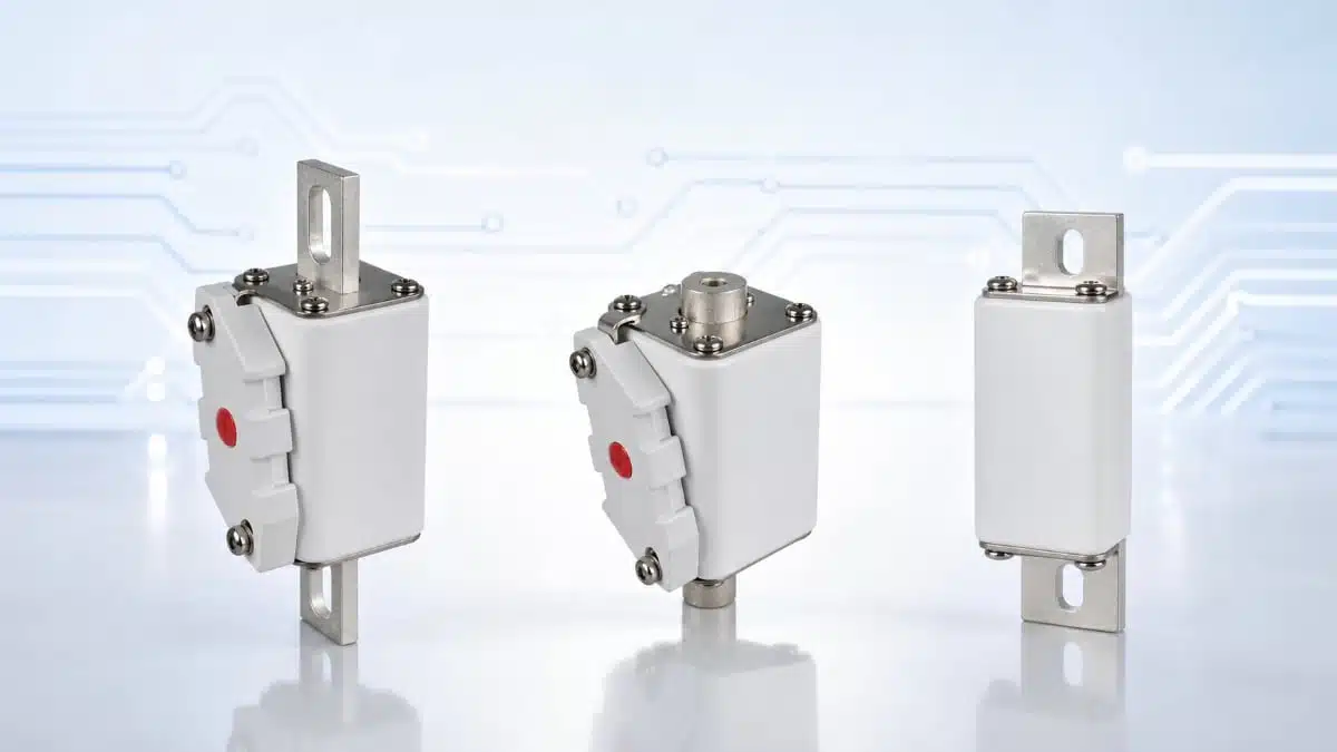
Bourns has expanded its POWrFuse high‑power fuse family with three new 1000 VDC semiconductor aR Class fuse series targeting power conversion, DC bus, and battery energy storage applications.
These fuse links address the growing need for robust overcurrent protection in high‑power DC systems, including battery energy storage systems and DC fast charging infrastructure.
The new series combine very high DC voltage ratings with high interrupting capability and compliance with key UL and IEC fuse standards, making them suitable for design engineers who need coordinated protection of power semiconductors and battery strings in demanding industrial and energy applications.
Key features and benefits
New POWrFuse series
- PF‑000100E Series high‑power fuse links designed for semiconductor and battery protection at 1000 VDC.
- PF‑01N100E Series semiconductor protection fuses for 800–1000 VDC systems.
- PF‑1NH100E Series semiconductor protection fuses for 1000 VDC applications with higher current ratings.
Standards and safety
- Designed to meet UL 248‑13 aR Class semiconductor fuse requirements (PF‑000100E Series).
- Designed to meet IEC 60269‑7 battery storage system fuse requirements (aBat Class, PF‑000100E Series).
- Designed to meet IEC 60269‑4 aR Class semiconductor fuse requirements (PF‑01N100E and PF‑1NH100E Series).
- High interrupting ratings up to 50 kA at 1000 VDC (according to manufacturer datasheet), enabling safe clearing of high‑energy DC faults without catastrophic failure.
Electrical performance
- 1000 VDC rated voltage with 50 kA interrupting current for PF‑000100E and PF‑1NH100E Series.
- 800/1000 VDC rated voltage with 50 kA interrupting capability for PF‑01N100E Series (according to manufacturer datasheet).
- Wide current rating coverage from 50 A up to 630 A across the three series, allowing protection of both lower‑power and high‑power DC subsystems.
Environmental and material aspects
- RoHS compliant according to the 2015/863 Directive.
- Classified as halogen free according to Bourns internal criteria for bromine and chlorine content.
- Suitable for designs that must meet restrictive substance and environmental compliance requirements.
For designers, the combination of high DC voltage, high interrupting capability, and appropriate standards compliance simplifies approvals and reduces risk when specifying overcurrent protection in DC systems above several hundred volts.
Typical applications
The PF‑000100E, PF‑01N100E, and PF‑1NH100E Series target a broad range of industrial and energy‑related DC systems where fault energy can be very high and semiconductor or battery packs must be protected quickly and selectively.
- Power conversion devices such as inverters, rectifiers, and DC‑DC converters in industrial and renewable energy systems.
- DC systems based on 800–1000 VDC buses, including centralized DC distribution architectures.
- DC common bus systems in multi‑converter installations where several power conversion stages share a common DC link.
- Battery energy storage systems (BESS) where fuses are required to protect battery strings, racks, or protection branches against short circuits.
- DC charging piles and fast chargers where high‑voltage DC outputs and power electronics must be protected from fault currents.
In practice, these fuses will often sit between the DC source (battery stack or rectified bus) and power electronic converters, or in sub‑branches of a common DC bus to provide selective fault isolation.
Application mapping by series
| Series | Typical system type | Installation example |
|---|---|---|
| PF‑000100E | DC systems, BESS | String‑level battery protection, DC source disconnect |
| PF‑01N100E | DC common bus systems 800–1000 VDC | Feeder fuses on shared DC bus |
| PF‑1NH100E | High‑current DC common bus and converters | Main DC bus incomer or large inverter branch |
Technical highlights
From an engineering perspective, the three POWrFuse series provide coordinated coverage over a wide current range while sharing similar high‑voltage and high‑breaking capacity characteristics.
Electrical ratings overview
| Series | Rated current range (A) | Rated voltage (VDC) | Interrupting rating | Protection class |
|---|---|---|---|---|
| PF‑000100E | 50–250 | 1000 | 50 kA at 1000 VDC | aR (semiconductor), aBat |
| PF‑01N100E | 50–450 | 800–1000 | According to manufacturer data | aR (semiconductor) |
| PF‑1NH100E | 400–630 | 1000 | According to manufacturer data | aR (semiconductor) |
A 1000 VDC rating is critical in modern DC architectures, where battery and DC link voltages routinely move into the 800–1000 VDC range to reduce current and cable size. The high interrupting rating in the tens of kiloamps means the fuse can clear worst‑case short circuits on low‑impedance DC buses without venting or case rupture, assuming proper coordination with upstream breakers and contactors.
Standards and coordination
- UL 248‑13 and IEC 60269‑4 define semiconductor fuse characteristics (aR Class), focusing on very fast operation to protect power semiconductors with low I²t limits.
- IEC 60269‑7 defines fuse links specifically intended for battery storage systems, covering aspects such as DC behavior, cycling, and system integration.
- Using fuses that are designed to these standards supports system‑level safety certification and helps ensure predictable behavior in coordination studies.
Because these are aR Class fuses, they provide short‑circuit protection for semiconductors and do not usually offer full range overload protection. Engineers must typically combine them with separate overcurrent devices or monitoring for overload and long‑term overcurrent conditions.
Mechanical formats and mounting
The new fuses are offered in bolt‑down and blade‑type formats suitable for high‑current busbar and cable terminations.
- PF‑000100E: Bolt‑down mounting type, optimized for compact high‑power DC installations where the fuse is directly bolted to busbars or lugs.
- PF‑01N100E: Available as bolt‑down, DIN blade, and flush‑end variants, allowing use in standardized fuse bases, switch‑disconnectors, or custom busbar assemblies.
- PF‑1NH100E: High‑current design aimed at busbar installations, according to the manufacturer documentation.
Using bolt‑down or blade mounting reduces contact resistance and improves thermal performance compared with lower‑current cartridge fuses, which is essential at high continuous currents.
Design‑in notes for engineers
When designing these POWrFuse high‑power fuses into a system, several practical considerations can help ensure reliable operation and compliance with safety requirements.
Selecting the appropriate series
- Choose PF‑000100E when both semiconductor and battery (aBat) protection are required at up to 1000 VDC, for example at pack or string level in BESS.
- Choose PF‑01N100E for 800–1000 VDC DC common bus and power conversion stages where flexible mounting (bolt‑down, DIN blade, flush‑end) is useful.
- Choose PF‑1NH100E for high‑current main DC feeds and large inverter branches where currents extend up to 630 A.
Current rating and derating
- Select the nominal current based on the continuous DC current of the protected branch, including ambient temperature and enclosure effects.
- Apply derating according to the manufacturer datasheet, taking into account expected operating temperature, cable or busbar cross‑section, and cooling conditions.
- Consider the maximum DC short‑circuit current and ensure that the fuse interrupting rating and associated hardware (busbars, terminations) can withstand the let‑through energy.
Coordination with semiconductors and batteries
- Use the aR Class time‑current characteristics and I²t data from the datasheet to coordinate the fuse with the safe operating area of IGBTs, MOSFETs, rectifiers, or thyristors.
- In battery systems, ensure that the fuse’s DC breaking performance aligns with the maximum fault current that can be delivered by the battery stack, including low‑temperature and high state‑of‑charge conditions.
- Combine these aR Class fuses with upstream or downstream devices that cover overload and lower‑level overcurrent protection, as aR fuses primarily address short‑circuit faults.
Mechanical integration and thermal aspects
- Ensure adequate creepage and clearance distances for 1000 VDC around fuse terminals, supports, and busbars.
- Design busbar or cable connections to minimize contact resistance and heat rise; follow the recommended tightening torques and surface finishes given in the datasheet.
- Consider positioning fuses to allow sufficient airflow or heat sinking, especially at higher continuous currents close to the upper end of each series range.
Serviceability and safety
- Use mounting arrangements (such as DIN blade bases or disconnect devices) that support safe replacement and isolation, especially in BESS and DC charging environments.
- Provide appropriate labeling and barriers to prevent accidental contact with live DC parts during service.
- Verify local code and standard requirements for DC overcurrent protection in battery and DC distribution systems, and ensure that the selected fuse series and installation method support the required approvals.
Source
This article is based on information provided in the official Bourns POWrFuse high‑power fuse new product release and associated manufacturer technical documentation and datasheets.