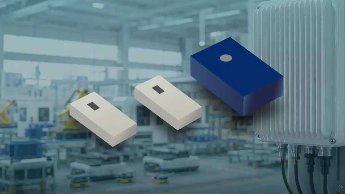
Bourns has introduced a set of compact LTCC band pass filters aimed at 5G C‑band RF front‑end designs, covering key frequency ranges between 3300 MHz and 5000 MHz.
These multilayer ceramic filter devices integrate multiple passive elements into a single monolithic structure, offering small footprints and controlled insertion loss for dense radio boards in base stations, FWA equipment, and private 5G networks.
Key features and benefits
- Compact LTCC multilayer construction that integrates inductive and capacitive elements into a single ceramic block, reducing discrete component count and layout complexity in RF front‑end filter networks.
- Frequency coverage tailored to 5G C‑band allocations, with models spanning 3300–4200 MHz and 4400–5000 MHz, suitable for eMBB, FWA, and private 5G deployments using C‑band carriers.
- Small package sizes down to 1.6 × 0.8 × 0.35 mm, enabling placement close to RFICs where routing space and matching network real estate are tight.
- Documented maximum insertion loss in the range of approximately 0.9 dB to 1.7 dB at 25 °C, helping designers budget gain and noise figure across the receive and transmit chains.
- Operating temperature ranges from −40 °C to +85 °C for two models and up to +105 °C for the largest device, making the series suitable for outdoor radio units and thermally stressed enclosures.
- RoHS‑compliant construction according to Bourns’ published compliance statement, supporting adoption in global telecom and industrial designs without additional material qualification effort.
Typical applications
These LTCC band pass filters target RF front‑end sections where narrowband filtering around the 5G C‑band is required and board space is limited. They can be used in both transmit and receive paths to define passbands and attenuate adjacent channels or out‑of‑band interference.
- 5G C‑band macro and small cells (eMBB) where compact filter networks must fit close to power amplifiers and low noise amplifiers.
- Fixed Wireless Access customer premises equipment and outdoor units using C‑band carriers for high‑capacity point‑to‑multipoint links.
- Private 5G networks in industrial campuses where frequency‑selective filtering helps manage coexistence with other wireless systems in shared spectrum.
- RF modules and front‑end boards in OEM radio subsystems that require documented, catalog LTCC filters rather than custom ceramic filters.
In practice, these devices will sit in the RF chain after the antenna and duplexer, often in combination with matching networks and additional filters to define the overall front‑end response.
Technical highlights
The FBP series currently consists of three LTCC band pass filter models with defined electrical characteristics and mechanical dimensions. The table below summarizes the key published parameters at 25 °C.
FBP LTCC band pass filters – key parameter
| Model | Size (mm) | Frequency range (MHz) | Max insertion loss @ 25 °C | Operating temperature |
|---|---|---|---|---|
| FBP1604N470L3 | 1.6 × 0.8 × 0.4 | 4400 – 5000 | 1.5 dB max | −40 °C to +85 °C |
| FBP1608N375L3 | 1.6 × 0.8 × 0.35 | 3300 – 4200 | 1.7 dB max | −40 °C to +85 °C |
| FBP2007N470L3 | 2.0 × 1.25 × 0.65 | 4400 – 5000 | 0.9 dB max | −40 °C to +105 °C |
All models are specified as LTCC band pass filters, meaning that they pass a defined band of frequencies and attenuate signals outside that band according to the manufacturer’s datasheet. The combination of compact mechanical size and controlled insertion loss allows integration into high‑density radio boards without significantly degrading system‑level performance.
From a practical standpoint, the lower insertion loss of the FBP2007N470L3 at higher temperatures can be beneficial in transmit chains where efficiency and thermal margins are critical, while the smaller footprints of the 1.6 mm devices are attractive near RFICs and in space‑constrained modules.
Design‑in notes for engineers
When designing these LTCC band pass filters into a 5G C‑band RF front‑end, engineers should consider both RF performance and mechanical integration aspects.
- Check frequency allocations and channel plan
Verify that the passband of the chosen FBP model aligns with the specific C‑band allocation and channelization for the target network and region, paying attention to edge frequencies and guard bands. - Budget insertion loss in the RF chain
Include the specified maximum insertion loss in the overall gain and noise figure calculations for the receive and transmit paths, particularly when cascading multiple filters and matching networks. - Account for temperature range and derating
Ensure the operating temperature range of the selected device matches the expected ambient and junction temperatures in outdoor radios, and review manufacturer curves for any temperature‑dependent performance shifts according to the datasheet. - Layout and grounding practices
Place the LTCC filters close to the associated RFICs with controlled impedance traces, solid RF ground, and minimal via inductance to preserve the intended filter response and reduce parasitics. - EMC and coexistence considerations
Use the band pass characteristics to help manage out‑of‑band emissions and susceptibility, especially in multi‑radio platforms where different bands share the same enclosure or antenna structures. - Qualification and compliance
Leverage the RoHS‑compliant status and documented characteristics in internal component libraries and AVL processes, and cross‑check long‑term availability through Bourns’ distribution channels.
For detailed S‑parameters, recommended land pattern, and performance plots over temperature and frequency, engineers should refer directly to the manufacturer datasheets for each part number rather than extrapolating beyond the published curves.
Source
This article is based on information provided in the official Bourns press release announcing the FBP series LTCC band pass filters for 5G C‑band RF front‑end designs, together with the associated product documentation available from the manufacturer.