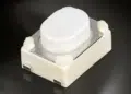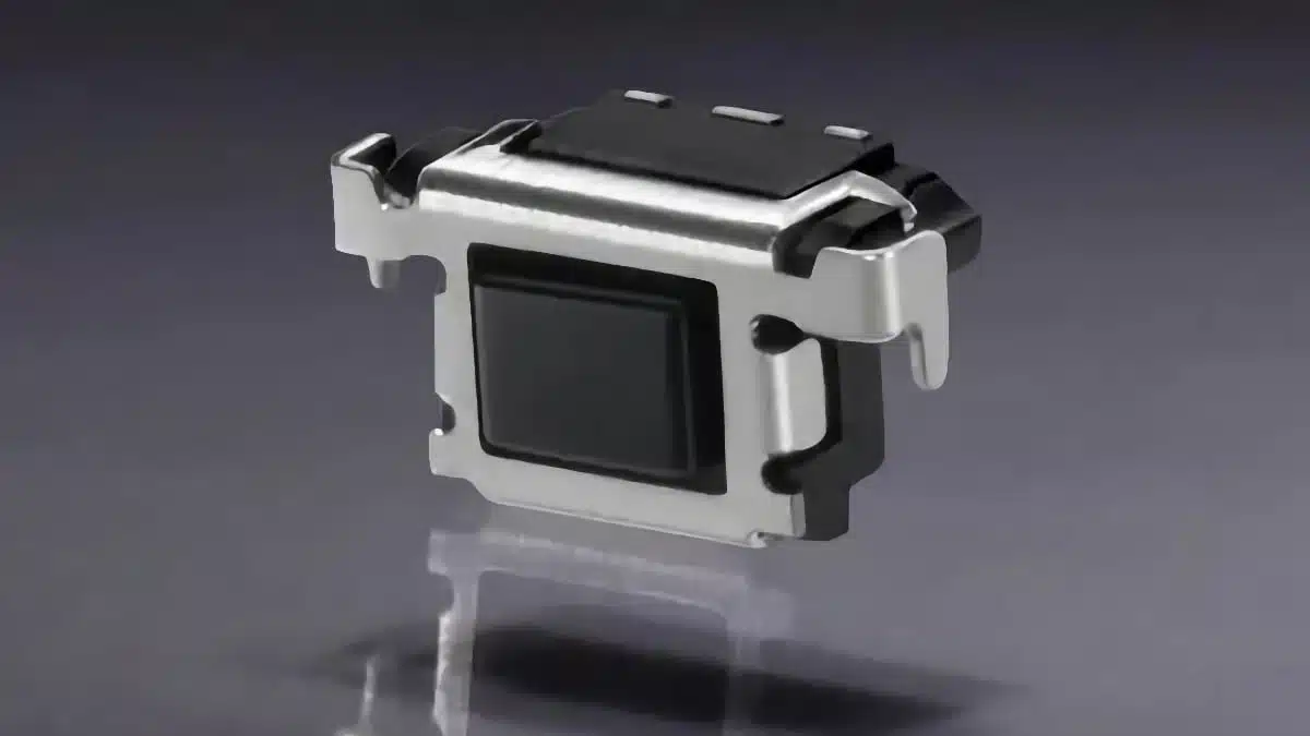
SCHURTER has introduced the TCSV4, a side-actuated SMT tactile switch for compact PCB assemblies and portable electronic equipment.
The SCHURTER TCSV4 4.5 × 2.25 × 2.6 mm component is intended for board-edge mounting, where it extends no more than 1.0 mm beyond the PCB edge.
Key features and benefits
- Compact 4.5 × 2.25 × 2.6 mm package for space-constrained PCB designs
- PCB edge-mount arrangement with a maximum 1.0 mm overhang beyond the board edge
- Side actuator offered with 1.6 N or 3.2 N actuation force
- Standard and L-shaped shield options
- Reflow-soldering compatibility to 260 °C for a maximum of 5 seconds
- 200,000-actuation service-life rating
- IP40 protection rating
- Tape-and-reel supply in 2,500-piece packaging units
- RoHS and REACH compliance
The new item is the TCSV4 series itself; the release identifies two actuation-force options and two shield configurations, but does not publish individual ordering codes or sub-family part numbers.
Technical highlights
| Parameter | Value | Notes |
|---|---|---|
| Component type | SMT tactile switch | Side actuator |
| Body dimensions | 4.5 × 2.25 × 2.6 mm | L × W × H |
| PCB-edge overhang | ≤ 1.0 mm | Edge-mount position |
| Actuation force | 1.6 N or 3.2 N | Two options |
| Switching range | 2–12 VDC | Electrical rating |
| Switching current | 10 µA–50 mA | Electrical rating |
| Initial contact resistance | ≤ 100 mΩ | Before life test |
| Contact resistance after life | ≤ 200 mΩ | After life test |
| Insulation resistance | > 100 MΩ | Published value |
| Operating temperature | −40 °C to +85 °C | Ambient range |
| Reflow exposure | 260 °C, 5 s max. | Process limit |
| Mechanical life | 200,000 actuations | Service-life rating |
| Protection class | IP40 | Solid-object protection |
The voltage and current range places the TCSV4 in low-power signal and user-interface switching rather than power-path switching. The published 10 µA lower current limit also matters in battery-operated products: contact performance should be verified at the actual wetting current and system voltage rather than only at the maximum 50 mA rating.
The 1.6 N and 3.2 N options permit a mechanical trade-off between lighter user actuation and a firmer switch feel. Selection should also consider enclosure geometry, actuator alignment, PCB retention, and the force transferred into the board edge during repeated use.
Typical applications
The announcement identifies digital cameras, audio players, sports headphones, Bluetooth accessories, and health-monitoring devices as target applications. Those applications are consistent with the compact package, board-edge geometry, 2–12 VDC switching range, 10 µA to 50 mA current range, and −40 °C to +85 °C operating-temperature rating.
- Portable cameras and imaging equipment: the 4.5 × 2.25 mm footprint and 1.0 mm maximum edge overhang support tightly packaged external control positions.
- Audio players and headphones: the low-voltage, low-current switching range supports user-interface functions rather than audio power switching.
- Bluetooth accessories: 2–12 VDC operation and the compact SMT format fit battery-powered control boards.
- Health-monitoring devices: the specified operating-temperature range and 200,000-actuation life support repeated low-power user-input functions, subject to full device-level validation.
The press release names these product categories, but it does not provide application-specific endurance, ingress, chemical-resistance, drop-test, or cleaning-process data. IP40 should not be read as moisture sealing or as a qualification for use in exposed outdoor, wash-down, or high-condensation environments.
Application fit
| Circuit position | Published support | Check before release |
|---|---|---|
| User-interface input | 2–12 VDC, 10 µA–50 mA | MCU input circuit |
| PCB-edge control | ≤ 1.0 mm overhang | Enclosure clearance |
| Portable equipment | 4.5 × 2.25 × 2.6 mm | Mechanical retention |
| Reflow SMT assembly | 260 °C, 5 s max. | Actual thermal profile |
| Repeated user operation | 200,000 actuations | Force and actuator travel |
For a board-edge switch, the circuit layout and mechanics are interdependent. Land pattern geometry, solder-joint loading, PCB thickness, enclosure aperture tolerances, and actuator alignment all need review together. A small package does not by itself guarantee resistance to side loading or torsional stress from a poorly aligned housing button.
Design-in notes for engineers
- Check the current TCSV4 datasheet for the approved land pattern, outline drawing, tape orientation, terminal dimensions, and complete reflow-profile limits before PCB release.
- Keep the switching load within 2–12 VDC and 10 µA–50 mA. Validate actual contact behaviour at the intended operating current, especially for ultra-low-current wake-up and logic-input circuits.
- Confirm that the selected 1.6 N or 3.2 N operating force is compatible with the enclosure button, actuator travel, ergonomic requirement, and board mounting.
- Assess PCB-edge clearance using the specified maximum 1.0 mm component overhang, including manufacturing tolerances and any protective housing features.
- Treat the 260 °C for 5 seconds figure as a stated process limit, not as a complete reflow-profile definition. Peak temperature, time above liquidus, ramp rate, and the assembled board thermal mass should be checked against the current manufacturer documentation.
- Do not use the IP40 rating as evidence of water, humidity, sweat, dust-sealing, or chemical-cleaning resistance. This should be verified under final operating conditions.
- Validate the switch in the finished mechanical assembly. Mechanical life is rated at 200,000 actuations, but end-product performance also depends on side loading, enclosure actuation geometry, solder-joint stress, vibration, and the actual electrical load.
Source
This information is based on the SCHURTER TCSV4 press release and the official product information accessible with the announcement. Engineers should consult the current manufacturer datasheet and associated documentation for final qualification, PCB footprint definition, soldering process approval, and design release.