











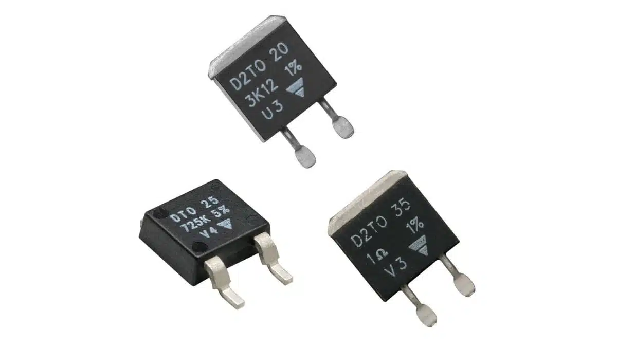
Vishay has introduced four evaluation kits for Sfernice thick-film SMD power resistors: D2TO 20, D2TO 35, DTO, and the combined DTO D2TO kit.
The Vishay kits provide selected SMD thick film resistors 1 Ω to 47 kΩ values in TO-263 D²PAK and TO-252 DPAK packages, helping engineers compare resistance values, package options, thermal paths, and series or parallel arrangements before committing to production parts.
Key features and benefits
- Four kits cover the D2TO20, D2TO35, DTO35, and combined DTO35 / D2TO35 resistor families.
- The kits contain AEC-Q200-qualified thick-film power resistors with ±1% tolerance and a stated ±150 ppm/°C TCR for the supplied values.
- D2TO20 is rated at 20 W with a 25 °C case temperature; D2TO35 and DTO35 are rated at 35 W under the same case-temperature condition.
- The D2TO packages use TO-263 D²PAK outlines, while DTO35 uses the smaller TO-252 DPAK outline.
- Each single-family kit contains 15 resistance values from 1 Ω to 47 kΩ, with four resistors per value, for 60 resistors in total.
- The combined DTO D2TO kit contains 12 resistance values in both package families, with four pieces of each value and model, for 96 resistors in total.
- The supplied test boards support four-resistor series or parallel configurations.
- All three resistor families use non-inductive thick-film elements and provide electrical isolation between the resistive element and metal tab.
- Resistance to soldering heat is specified at 270 °C for 10 s, and the devices are classified MSL 1.
Technical highlights
The sample-kit announcement names the following ordering numbers:
| Resistor series | Sample-kit name | Ordering number | Package |
|---|---|---|---|
| D2TO20 | D2TO 20 Sample Kit | ACCLFFD2TO20SPLKIT | TO-263 D²PAK |
| D2TO35 | D2TO 35 Sample Kit | ACCLFFD2TO35SPLKIT | TO-263 D²PAK |
| DTO35 | DTO Sample Kit | ACCLFFDTOSPLKIT | TO-252 DPAK |
| DTO35 and D2TO35 | DTO D2TO Sample Kit | ACCLFFDTOD2TOSPLKT | TO-252 and TO-263 |
The press release identifies the four kits, but only three current kit documents were publicly available in the source sweep: D2TO 20, DTO, and DTO D2TO. The combined-kit document identifies D2TO35 as its TO-263 member. The individual D2TO 35 sample-kit document was not located publicly and should be confirmed with Vishay before relying on its kit contents.
The release quotes a 1 Ω to 47 kΩ sample range. That is a deliberately selected subset rather than the full family range. The current datasheets specify 0.01 Ω to 550 kΩ for D2TO20 and D2TO35, and 0.016 Ω to 700 kΩ for DTO35.
| Parameter | D2TO20 | D2TO35 | DTO35 |
|---|---|---|---|
| Package | TO-263 D²PAK | TO-263 D²PAK | TO-252 DPAK |
| Rated power | 20 W | 35 W | 35 W |
| Rating condition | 25 °C case | 25 °C case | 25 °C case |
| Resistance range | 0.01 Ω to 550 kΩ | 0.01 Ω to 550 kΩ | 0.016 Ω to 700 kΩ |
| Limiting voltage | 500 V | 500 V | 500 V |
| Operating range | −55 °C to +155 °C | −55 °C to +175 °C | −55 °C to +175 °C |
| Thermal resistance | 6.5 °C/W | 4.28 °C/W | 4.28 °C/W |
| Inductance | ≤ 0.1 µH | ≤ 0.1 µH | ≤ 0.1 µH |
| Dielectric strength | 2000 V RMS | 2000 V RMS | 1500 V RMS |
D2TO20 and D2TO35 share the same TO-263 package outline and solder-pad recommendation. The published package drawing gives a body length of 10.5 mm, width of 8.8 mm, and maximum component weight of 2.2 g. DTO35 uses the smaller TO-252 outline, with a package body length of 12.4 mm and width of 6.82 mm; maximum weight is 2 g.
The D2TO35 datasheet is revised 10 September 2026. The D2TO20 datasheet is revised 23 February 2024, while the publicly available DTO35 datasheet is revised 10 November 2021. Vishay’s 2026 kit documents identify these as the applicable supporting specifications, but the older DTO35 datasheet revision should be checked again at final component release.
Application fit
These are high-power board-mounted resistors, not 20 W or 35 W parts in an unrestricted ambient-air PCB installation. Their full ratings are specified at controlled case temperature, so the final usable dissipation depends on the solder joint, copper area, board material, airflow, mounting orientation, nearby heat sources, and available cooling path.
| Circuit position | Supporting published ratings | Selection point |
|---|---|---|
| Bleeder or discharge resistor | 500 V limiting voltage, 20 W or 35 W case rating | Check continuous voltage and discharge-pulse energy |
| Precharge or inrush limiting | 0.01 Ω or 0.016 Ω lower resistance options, pulse curves | Validate repetitive pulse energy and fault duration |
| Braking or load resistor | 35 W case rating, +175 °C element limit | Design the board or heatsink thermal path |
| Snubber or damping resistor | ≤ 0.1 µH inductance, impedance plots to 300 MHz | Check waveform, repetition rate, and pulse-energy curve |
| Power-stage divider or damping network | ±1% sample tolerance, selected ±150 ppm/°C TCR values | Check tolerance and TCR at the selected resistance |
| Automotive or high-reliability PCB | AEC-Q200 qualification, MSL 1, 270 °C / 10 s soldering test | Qualification does not replace system-level validation |
The 35 W D2TO35 and DTO35 ratings are both specified at a 25 °C case temperature with of 4.28 °C/W and a maximum resistive-element temperature of +175 °C. That supports use where a substantial heat-removal path can be engineered through the package tab and PCB.
The smaller DTO35 package has the same nominal 35 W case-temperature rating as D2TO35, but its package geometry, board footprint, copper spreading area, and mounting arrangement remain selection variables. The combined kit is therefore useful where engineers need to compare the thermal behaviour of TO-252 and TO-263 layouts under representative board conditions rather than select only on headline wattage.
The published thermal-management measurements illustrate the distinction between case-rated and board-level power. On a double-sided FR4 HTG board measuring 39 mm × 30 mm × 1.6 mm with 70 µm copper and thermal vias, the application note reports 3.1 W for D2TO20, 3.5 W for D2TO35, and 4.5 W for DTO35 at 25 °C ambient. These are test-board results, not general application ratings.
Design-in notes for engineers
- Treat the 20 W and 35 W figures as case-temperature ratings. Establish the allowed resistance-element, tab, solder-joint, and PCB temperatures under maximum ambient and load conditions before setting a continuous-power limit.
- Use the current power resistor thermal design guidance principle: verify copper spreading, board stack-up, via structure, airflow, enclosure temperature, and neighbouring heat sources on the final assembly.
- Vishay’s thermal note identifies the PCB as the limiting thermal element in many practical installations. Standard FR4, FR4 HTG / FR5, insulated-metal substrates, copper thickness, pad area, thermal vias, and solder voiding all materially affect dissipation.
- Use the specified land pattern. For D2TO, the published solderable-contact footprint is 8.1 mm × 15.4 mm. For DTO35, the published footprint dimensions include 8.51 mm and 7.87 mm pad extents. Confirm the exact copper geometry in the applicable drawing before PCB release.
- Do not mount D2TO or DTO devices on both sides of the supplied test PCB. The kit documentation warns that this deteriorates thermal performance.
- Apply the recommended lead-free thermal profile in J-STD-020C. The resistor documents specify resistance to soldering heat at 270 °C for 10 s, while the thermal-management note gives a 250 °C lead-free peak classification temperature and a maximum component soldering temperature of 270 °C.
- Check the 500 V limiting-element voltage and 750 V maximum overload voltage separately from the nominal resistance and continuous power requirement. Startup, capacitor discharge, switching transients, load dump, and fault modes may set the real design limit.
- Evaluate pulse energy using the applicable D2TO20, D2TO35, or DTO35 energy curve. The published curves apply to a single pulse on a cold resistor at 25 °C and durations up to 100 ms; they do not establish repetitive-pulse capability under elevated operating temperature.
- The supplied ±1% tolerance and ±150 ppm/°C TCR apply to the selected kit values, not necessarily every resistance within the full series range. Verify the resistance-specific tolerance and TCR table for the intended production part number.
- AEC-Q200 is a passive-component stress-test qualification. It does not constitute vehicle-level approval or confirm suitability for a particular safety, automotive, traction, industrial-drive, or energy-storage application.
- D2TO20, D2TO35, and DTO35 have documented biased-humidity, temperature-cycling, vibration, mechanical-shock, board-flex, terminal-strength, and operational-life tests. These published qualification results do not replace system-level validation under the final vibration, humidity, temperature-cycling, and electrical-load profile.
- Confirm production availability, lead time, packaging, approved resistance value, and ordering code with Vishay or an authorised distributor. The announcement states that samples are available with four-week lead times, but commercial status and delivery conditions can change.
Further reading
- Vishay Unveils 120W High Energy Power Resistor
- Vishay Releases Automotive Pulse Robust Power Resistor
- Vishay Automotive Current Sense Resistors Combine High Power and Wide Resistance for Better Accuracy by Eliminating Parallel Elements
Source
This information is based on the Vishay press release and official Vishay Sfernice sample-kit, datasheet, and thermal-management documentation. Engineers should consult the current manufacturer datasheet, layout recommendation, qualification data, and application documentation for final component qualification and design release.
References
- Vishay Intertechnology Thick Film Resistor Sample Kits Simplify Device Selection and Validation
- Vishay D2TO 20 Sample Kit, document 51115, revision 31-Jul-2026
- Vishay DTO Sample Kit, document 51117, revision 31-Jul-2026
- Vishay DTO D2TO Sample Kit, document 51118, revision 31-Jul-2026
- Vishay D2TO20 Surface Mount Power Resistor, document 51055, revision 23-Feb-2024
- Vishay D2TO35 Surface Mount Power Resistor, document 51058, revision 10-Sep-2026
- Vishay DTO35 Surface Mounted Power Resistor, document 51078, revision 10-Nov-2021
- Vishay Thermal Management on SMD Thick Film Resistors, document 52027, revision 03-Aug-2026












