











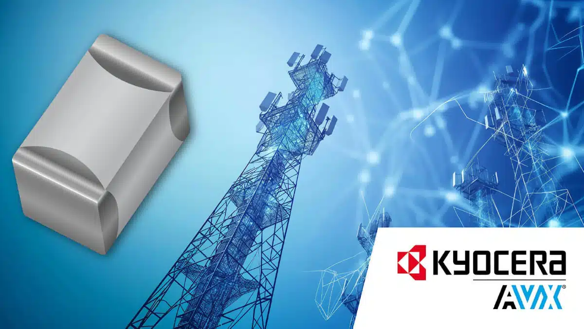
KYOCERA AVX has expanded its KGU Series of C0G (NP0) RF multilayer ceramic capacitors with an ultraminiature 0201 case size.
The addition targets densely populated RF circuits that need stable capacitance, low loss, and repeatable high-frequency behaviour in wireless, satellite, and broadband equipment. The KYOCERA AVX KGU range now spans five EIA chip sizes, from 01005 to 0805, offering a common RF capacitor family for designs where footprint reduction must not compromise tuning accuracy or signal integrity.
Key features and benefits
- New 0201 option: The new ultraminiature case size supports further PCB area reduction in RF front ends, matching networks, tuning circuits, and compact radio modules.
- C0G (NP0) Class I dielectric: This dielectric provides a temperature coefficient of capacitance of 0 ±30 ppm/°C and virtually zero voltage coefficient, helping preserve circuit tuning as temperature and applied DC bias change.
- Ultra-low ESR and high Q: Low equivalent series resistance reduces loss in RF current paths, while a high quality factor supports efficient resonant and impedance-matching networks.
- High self-resonant frequency: The series is intended for high-frequency applications in which the capacitor must retain capacitive behaviour at the operating frequency.
- Tight capacitance tolerances: Selected values are available with tolerances down to ±0.05 pF, an important parameter for narrowband tuning and frequency-setting circuits.
- Assembly-focused construction: KYOCERA AVX states that the components offer thermal and mechanical resilience intended to reduce risks such as cracking and tombstoning during high-volume assembly.
- RoHS compliant and tape-and-reel supplied: Standard packaging supports automated placement processes and volume manufacturing.
For a broader introduction to the construction, dielectric behaviour, and application differences of MLCC and ceramic capacitors, see the related knowledge article.
Technical highlights
| Parameter | KGU Series range |
|---|---|
| Dielectric | C0G (NP0), Class I ceramic |
| EIA case sizes | 01005, 0201, 0402, 0603, 0805 |
| Rated voltage | 6.3 V to 250 V, according to the launch announcement |
| Capacitance range | 0.1 pF to 100 pF |
| Minimum stated tolerance | ±0.05 pF |
| Operating temperature | -55°C to +125°C, according to the launch announcement |
| Electrode system | Tin/nickel-plated copper base-metal electrodes |
| Compliance | RoHS compliant |
The manufacturer product-family page presents a partly different general range—16 V to 250 V, -40°C to +125°C, and tolerances down to ±0.5 pF—so engineers should confirm the exact ratings, tolerance code, temperature specification, and availability for each 0201 part number according to the current manufacturer datasheet.
Typical applications
KYOCERA AVX identifies the KGU Series for RF functions including:
- Bypass and local RF decoupling networks
- AC-coupling and DC-blocking positions
- Impedance-matching networks
- RF and microwave filter networks
- Tuning circuits
- High-Q frequency-setting and resonant circuits
- Subscriber wireless devices
- 802.11 Wi-Fi equipment
- Cellular base stations
- Broadband wireless infrastructure
- Satellite communication hardware
- Public-safety radio systems
Application fit
| Circuit requirement | Why the KGU Series may fit |
|---|---|
| Compact RF matching network | The 0201 option can reduce component area where a carefully controlled low-value capacitor is required. |
| Temperature-stable tuning | C0G dielectric behaviour helps minimise capacitance drift over temperature. |
| Narrow-tolerance frequency control | Sub-picofarad tolerance options can be relevant where small capacitance shifts affect centre frequency or impedance matching. |
| Low-loss resonant circuit | High Q and low ESR are desirable in resonators, filters, and frequency-selective networks. |
| Dense wireless module | The 01005 through 0805 size coverage gives designers flexibility to balance RF performance, power handling, manufacturability, and PCB area. |
Design-in notes for engineers
- Select by RF performance, not capacitance alone. At RF frequencies, ESR, Q, self-resonant frequency, mounting-pad parasitics, and tolerance can be as important as the nominal capacitance.
- Treat the 0201 footprint as part of the RF network. Pad geometry, via placement, ground-return inductance, solder fillet size, and component orientation can change the effective impedance of a very small capacitor.
- Verify S-parameters at the intended frequency. A capacitance value measured at a low test frequency does not fully describe behaviour in a GHz-range matching or filtering network; use the manufacturer’s available RF data and simulation models where applicable.
- Check the capacitor’s operating point. Although C0G dielectric offers excellent capacitance stability, the selected part must still meet voltage, RF current, dissipation, temperature, and reliability requirements in the completed circuit.
- Review assembly capability. The 0201 format can deliver useful density gains but raises demands on stencil design, placement accuracy, reflow profiling, inspection, and repair strategy.
- Validate the final layout. Prototype-level impedance measurements and final-network tuning remain essential when replacing a larger component with a smaller case size, particularly in narrowband or high-Q circuits.
- Confirm ordering details early. Match the exact capacitance code, tolerance, voltage rating, termination option, packaging quantity, and lifecycle status to the approved bill of materials.
For engineers comparing possible capacitor technologies and suppliers in this application area, the High-Q RF & Microwave MLCCs: A Cross-Vendor Benchmark provides additional RF-focused context.
Further reading
- MLCC and Ceramic Capacitors
- High-Q RF & Microwave MLCCs: A Cross-Vendor Benchmark
- Knowles Extends Range and Performance of C0G MLCC Capacitors
- Enabling the 800 V AI Server Era: How C0G High-Voltage MLCC Supports Next-Generation Power Architectures
Source
This article is based on the KYOCERA AVX manufacturer press release and the KGU Series product-family information. Engineers should consult the current manufacturer datasheet, RF models, and product documentation for final component selection, qualification, and design release.












