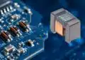


Bourns SM9127AL planar isolation transformers help cut EMI in modern SiC and GaN gate‑driver PSUs by turning PCB geometry into a controlled design parameter.
Switch‑mode power stages based on SiC and GaN devices push switching frequencies and edge rates into a regime where the isolation transformers in the gate‑driver PSU becomes a major EMI conduit rather than a benign magnetic component. The SM9127AL series uses PCB‑based winding geometry to control interwinding capacitance and leakage inductance, enabling measurable conducted‑EMI reduction in high‑frequency gate‑drive supplies.
Key features and benefits
Planar transformer replace traditional wire‑wound magnetics with PCB‑embedded windings and a low‑profile core, which fundamentally changes how parasitic elements are defined and controlled.
- Controlled interwinding capacitance
In planar construction, the position of each winding within the PCB stack‑up and the dielectric thickness between layers are set by design, so the effective interwinding capacitance and winding losses are highly predictable lot‑to‑lot rather than dependent on operator‑driven layer placement. - Defined leakage inductance as a design parameter
In LLC resonant converter topologies, leakage inductance is part of the resonant tank, not an unwanted parasitic; with planar geometry, leakage inductance is set by the relative winding placement and overlap on the PCB, which makes it a repeatable design parameter instead of a tolerance issue. - Significant conducted EMI reduction
Measured results reported by the manufacturer show on the order of 10–15 dBµV reduction in conducted EMI across the 1 MHz to 100 MHz band when using planar transformers designed for SiC and GaN gate‑driver supplies, directly targeting the frequency range where switching harmonics tend to be most problematic. - Low‑profile isolation for dense layouts
The SM9127AL series offers a 3.2 mm profile, enabling high‑isolation magnetics in flat designs such as gate‑driver PCBs for power modules, where vertical clearance over the isolation barrier is limited. - High isolation ratings
The series is specified at 850 VDC working voltage with 6000 VDC Hi‑Pot capability, in line with robust isolation requirements for gate drivers in high‑voltage SiC and GaN converter systems, with AEC‑Q200 qualification positioning the devices for automotive and other demanding applications. - Surface‑mount and reflow compatible
SM9127AL planar transformers use a surface‑mount package compatible with standard reflow processes, which simplifies assembly, avoids manual transformer insertion and supports automated optical inspection thanks to the repeatable geometry.
SM9127AL series – core data snapshot
The table below summarizes the key isolation and mechanical characteristics as presented by the manufacturer; exact per‑part values remain according to the manufacturer datasheet.
| Parameter | SM9127AL series value |
|---|---|
| Construction | Planar isolation transformer, PCB‑winding based |
| Profile height | 3.2 mm |
| Working voltage | 850 VDC |
| Hi‑Pot test voltage | 6000 VDC |
| Qualification | AEC‑Q200 |
| Mounting | Surface‑mount, reflow compatible |
Typical applications
Planar gate‑drive isolation transformers such as the SM9127AL series are targeted at modern high‑performance power conversion platforms where fast switching, high dv/dt and tight EMI budgets coexist.
- SiC‑based DC‑DC gate‑driver power supplies in traction inverters, industrial drives and high‑power UPS systems.
- GaN‑based gate‑driver supplies in compact power‑factor‑correction (PFC) stages, high‑density AC‑DC front ends and server or telecom bricks.
- LLC resonant converter topologies used for isolated auxiliary supplies, where leakage inductance and transformer parasitics have a direct impact on efficiency, control and EMI.
- Automotive and transportation applications requiring AEC‑Q200 qualified magnetics, including on‑board chargers, battery management systems and high‑voltage ECUs.
- Any isolated gate‑driver PSU architecture where conducted EMI in the 1–100 MHz band is a limiting factor for compliance or system‑level noise margins.
In practice, design engineers can treat the SM9127AL series as a geometry‑controlled isolation element that both delivers the required gate‑driver power and actively assists in meeting EMI targets, instead of being an opaque source of parasitics to be mitigated elsewhere.
Technical highlights
The technical differentiator of planar transformers in gate‑driver applications is that geometry becomes the main design variable for both useful and parasitic inductances and capacitances.
Interwinding capacitance and displacement current
When a SiC or GaN switch transitions at high dv/dt, every edge on the primary of the isolation transformer drives a displacement current through the interwinding capacitance into the secondary and ultimately into the ground plane. In traditional wire‑wound construction, that capacitance is influenced by winding order, insulation build and mechanical tolerances.
With planar transformers:
- The interwinding capacitance is defined by the overlap area of copper windings across PCB layers, the dielectric constant of the PCB material and the exact dielectric thickness between layers.
- These parameters are fixed by the PCB stack‑up, so the displacement current path is predictable and can be minimized or shaped as needed, which directly reduces conducted EMI through the isolation barrier.
Leakage inductance as part of the LLC resonant tank
In LLC resonant converters, leakage inductance is part of the resonant tank rather than something to be eliminated. The effective resonant inductance Lres is often composed of a combination of magnetizing inductance and leakage inductance contributions according to the topology used. In planar transformers, the leakage inductance is controlled by the degree of coupling between primary and secondary windings via:
- Lateral alignment and overlap on the PCB layers.
- Number of turns and track width.
- Use of interleaved or non‑interleaved winding arrangements.
This means that the same component can be tuned to provide the appropriate leakage inductance for a given LLC design, while maintaining tight tolerance and repeatability across production.
Conducted EMI performance
The manufacturer’s measured data shows that moving to planar construction with controlled interwinding capacitance yields a reduction of approximately 10–15 dBµV in conducted EMI over the 1 MHz to 100 MHz frequency band. This is significant because:
- That band covers many of the higher‑order harmonics of typical SiC and GaN switching waveforms, which tend to couple via parasitic capacitances.
- A reduction of this magnitude can translate into easier compliance with CISPR‑class EMI limits and reduced filtering burden in the gate‑driver PSU and main power path.
Isolation, safety and qualification
For high‑energy SiC and GaN converters, isolation is both a safety and functional requirement. The SM9127AL series addresses this with:
- 850 VDC working voltage rating, aligned with many mid‑to‑high voltage bus architectures.
- 6000 VDC Hi‑Pot capability for production testing and safety margin.
- AEC‑Q200 qualification supporting use in automotive and other environments with strict reliability and robustness standards.
Exact creepage and clearance distances, insulation system classification and detailed safety standard references should be taken from the manufacturer datasheet and safety approvals documentation.
Design‑in notes for engineers
For engineers working on SiC and GaN gate‑driver supplies, planar transformers like the SM9127AL series introduce both opportunities and constraints that differ from traditional wire‑wound magnetics.
- Treat parasitics as design knobs, not afterthoughts
Interwinding capacitance and leakage inductance are inherently tied to PCB geometry, so they can be used as explicit design parameters when shaping EMI behavior and resonant characteristics, rather than being tolerated as uncontrolled side effects. - Integrate PCB stack‑up into magnetic design
Because winding positions and dielectric thicknesses are part of the PCB, early collaboration between magnetics design and PCB layout is advisable; layer ordering, material choice and thickness will impact both transformer behavior and overall EMI. - Consider gate‑driver PSU topology
In LLC resonant converters, use the specified leakage inductance and magnetizing inductance data from the manufacturer when calculating the resonant tank; verify that the planar transformer’s tolerances are compatible with your soft‑switching and efficiency targets. - Account for dv/dt stress and EMI budgets
High dv/dt edges of SiC and GaN devices make displacement current through interwinding capacitance a primary EMI path; when evaluating adoption of planar magnetics, consider the reported EMI reduction against your system‑level filter design and compliance targets. - Leverage low profile near hot modules
The 3.2 mm profile aids placement close to power modules in compact gate‑driver boards; however, thermal modeling should still include proximity to hot devices and copper planes to ensure the transformer operates within its rated temperature range. - Check isolation margins in system context
While the series is rated for 850 VDC working and 6000 VDC Hi‑Pot, system‑level isolation requirements depend on standards, pollution degree and overvoltage category; confirm that creepage, clearance and insulation system match your safety case. - Verify AEC‑Q200 and reliability data
For automotive or harsh industrial applications, review the AEC‑Q200 reports, life test data and derating guidance from the manufacturer to align component stress with expected mission profiles.
Practical selection hints
When selecting a specific SM9127AL part number for an isolated gate‑driver supply:
- Start from gate‑driver rail requirements (for example, ±15 V or unipolar supplies) and identify the turns ratio options that fit your PSU topology.
- Cross‑check the leakage and magnetizing inductance values with your resonant or flyback design equations to ensure the transformer supports desired switching frequency and soft‑switching behavior.
- Evaluate EMI performance claims in the context of your target standards and existing filter architecture, considering laboratory validation with LISN measurements in the 1–100 MHz band.
Source
This article is based on the manufacturer’s official product information, video presentation, application note and white paper describing the SM9127AL planar isolation transformer series, with technical interpretations aimed at design engineers and component purchasing professionals.
References
- SM9127AL planar isolation transformer product page
- Advantages of planar transformers in LLC resonant topologies – application note
- Isolated gate driver PSU considerations for modern power conversion applications – white paper
- How planar transformers cut EMI in SiC & GaN gate driver isolation – Bourns video