





Passive Components Blog
No Result
View All Result
  • Home
  • NewsFilter
    • All
    • Aerospace & Defence
    • Antenna
    • Applications
    • Automotive
    • Capacitors
    • Circuit Protection Devices
    • electro-mechanical news
    • Filters
    • Fuses
    • Inductors
    • Industrial
    • Integrated Passives
    • inter-connect news
    • Market & Supply Chain
    • Market Insights
    • Medical
    • Modelling and Simulation
    • New Materials & Supply
    • New Technologies
    • Non-linear Passives
    • Oscillators
    • Passive Sensors News
    • Resistors
    • RF & Microwave
    • Telecommunication
    • Weekly Digest

    Designing a Custom Core Transformer for 10 kW LLC Data Center Power Stages

    Magnetics Design in High‑Frequency GaN Converters

    ECIA Industry Pulse April 2026: Sentiment Cools but Stays Strong

    Industrial Passive Components Markets and Technologies 2026

    Automotive Passive Components Technology Dossier

    Samsung Electro-Mechanics Signs 1.5T KRW Silicon Capacitor AI Contract

    Murata Expands Thermistor Production Capacity at Yokaichi Plant

    Hirose Expands Compact High‑Voltage EV connectors

    Qi2 Wireless Charging: Inductors, Capacitors and EMC Filters

    Trending Tags

    • Ripple Current
    • RF
    • Leakage Current
    • Tantalum vs Ceramic
    • Snubber
    • Low ESR
    • Feedthrough
    • Derating
    • Dielectric Constant
    • New Products
    • Market Reports
  • VideoFilter
    • All
    • Antenna videos
    • Capacitor videos
    • Circuit Protection Video
    • Filter videos
    • Fuse videos
    • Inductor videos
    • Inter-Connect Video
    • Non-linear passives videos
    • Oscillator videos
    • Passive sensors videos
    • Resistor videos

    Magnetics Design in High‑Frequency GaN Converters

    Qi2 Wireless Charging: Inductors, Capacitors and EMC Filters

    Two‑capacitor paradox explained for engineers

    Capacitances of Nonlinear MLCCs: What Datasheets Don’t Tell You

    Tapped Inductor Buck Converter Fundamentals

    Planar vs Conventional Transformer: When it Make Sense

    Modeling Fringing Field Losses in Inductors & Transformers

    Why Power Inductors Use a Ferrite Core With an Air Gap

    Transformer-Based Power-Line Harvester Magnetic Design

    Trending Tags

    • Capacitors explained
    • Inductors explained
    • Resistors explained
    • Filters explained
    • Application Video Guidelines
    • EMC
    • New Products
    • Ripple Current
    • Simulation
    • Tantalum vs Ceramic
  • Knowledge Blog
  • DossiersNew
  • Suppliers
    • Who is Who
  • PCNS
    • PCNS 2025
    • PCNS 2023
    • PCNS 2021
    • PCNS 2019
    • PCNS 2017
  • Events
  • Home
  • NewsFilter
    • All
    • Aerospace & Defence
    • Antenna
    • Applications
    • Automotive
    • Capacitors
    • Circuit Protection Devices
    • electro-mechanical news
    • Filters
    • Fuses
    • Inductors
    • Industrial
    • Integrated Passives
    • inter-connect news
    • Market & Supply Chain
    • Market Insights
    • Medical
    • Modelling and Simulation
    • New Materials & Supply
    • New Technologies
    • Non-linear Passives
    • Oscillators
    • Passive Sensors News
    • Resistors
    • RF & Microwave
    • Telecommunication
    • Weekly Digest

    Designing a Custom Core Transformer for 10 kW LLC Data Center Power Stages

    Magnetics Design in High‑Frequency GaN Converters

    ECIA Industry Pulse April 2026: Sentiment Cools but Stays Strong

    Industrial Passive Components Markets and Technologies 2026

    Automotive Passive Components Technology Dossier

    Samsung Electro-Mechanics Signs 1.5T KRW Silicon Capacitor AI Contract

    Murata Expands Thermistor Production Capacity at Yokaichi Plant

    Hirose Expands Compact High‑Voltage EV connectors

    Qi2 Wireless Charging: Inductors, Capacitors and EMC Filters

    Trending Tags

    • Ripple Current
    • RF
    • Leakage Current
    • Tantalum vs Ceramic
    • Snubber
    • Low ESR
    • Feedthrough
    • Derating
    • Dielectric Constant
    • New Products
    • Market Reports
  • VideoFilter
    • All
    • Antenna videos
    • Capacitor videos
    • Circuit Protection Video
    • Filter videos
    • Fuse videos
    • Inductor videos
    • Inter-Connect Video
    • Non-linear passives videos
    • Oscillator videos
    • Passive sensors videos
    • Resistor videos

    Magnetics Design in High‑Frequency GaN Converters

    Qi2 Wireless Charging: Inductors, Capacitors and EMC Filters

    Two‑capacitor paradox explained for engineers

    Capacitances of Nonlinear MLCCs: What Datasheets Don’t Tell You

    Tapped Inductor Buck Converter Fundamentals

    Planar vs Conventional Transformer: When it Make Sense

    Modeling Fringing Field Losses in Inductors & Transformers

    Why Power Inductors Use a Ferrite Core With an Air Gap

    Transformer-Based Power-Line Harvester Magnetic Design

    Trending Tags

    • Capacitors explained
    • Inductors explained
    • Resistors explained
    • Filters explained
    • Application Video Guidelines
    • EMC
    • New Products
    • Ripple Current
    • Simulation
    • Tantalum vs Ceramic
  • Knowledge Blog
  • DossiersNew
  • Suppliers
    • Who is Who
  • PCNS
    • PCNS 2025
    • PCNS 2023
    • PCNS 2021
    • PCNS 2019
    • PCNS 2017
  • Events
No Result
View All Result
Passive Components Blog
No Result
View All Result

Coilcraft Unveils Molded Power Inductors for High‑Current VRMs

8.4.2026
Reading Time: 7 mins read
A A

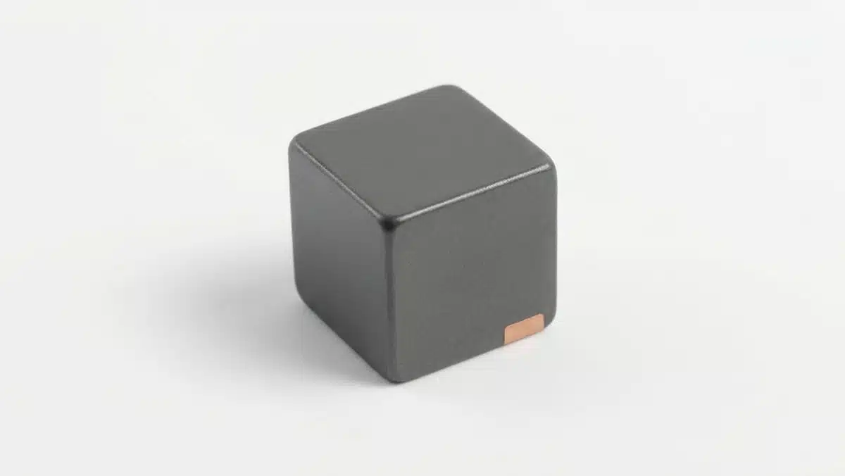
Coilcraft releases KTA5050 series family of molded, shielded power inductors with ultra‑low inductance values optimized for modern low‑voltage, high‑current DC‑DC converters in compact 5.6 × 5.2 × 5.0 mm packages.

These parts extend the KTA molded power inductor family toward higher power levels while maintaining low losses and robust AEC‑Q200 performance for demanding CPU, GPU, ASIC, and automotive power rails.

RelatedPosts

Coilcraft Introduces SMT Current Sense Transformers for High‑Performance Power Electronics

Coilcraft Releases TLVR Inductors for High Density VRMs and PoL Converters

Coilcraft Releases Automotive Common Mode Chokes

Key features and benefits

The KTA5050 inductors are designed as low‑inductance power chokes for fast transient, high‑current multiphase regulators where board area and efficiency are both critical.

  • Inductance range from approximately 65 nH up to around 600 nH, covering typical values used in single‑phase and multiphase VRMs and point‑of‑load (PoL) converters according to manufacturer datasheet.
  • Compact molded shielded package of about 5.6 mm length, 5.2 mm width, and 5.0 mm height, supporting high current density in space‑constrained server and automotive boards.
  • Composite magnetic core optimized for low AC losses at high switching frequencies used in modern buck converters.
  • Very low DC resistance (DCR) values to minimize conduction loss and improve overall converter efficiency, especially at high load currents.
  • Soft saturation behavior to support large transient load steps without abrupt inductance collapse, which helps keep output voltage within tight tolerance during spikes.
  • AEC‑Q200 qualification and maximum part temperature rating up to 165 °C, enabling robust operation in engine compartments and other harsh environments.
  • RoHS‑compliant, halogen‑free construction and compatibility with standard lead‑free reflow profiles according to Coilcraft specifications.

In practical terms, the combination of low inductance and low inductor losses makes KTA5050 well suited to high switching frequencies, where small inductance values allow tight transient control without sacrificing efficiency. The molded shielded construction also reduces radiated EMI and simplifies layout around sensitive digital ICs.

Typical applications

KTA5050 targets high‑performance power stages where transient performance, efficiency, and thermal margins are critical.

  • Multiphase voltage regulator modules (VRMs) for server and data‑center CPUs and GPUs.
  • PoL regulators for high‑current ASICs and SoCs in networking, AI acceleration, and storage systems.
  • High‑current core and memory rails on graphics cards, accelerator cards, and high‑end embedded compute modules.
  • Automotive ECUs and domain controllers, including ADAS, infotainment, and powertrain control units where AEC‑Q200 and elevated temperature capability are required.
  • Industrial and telecom power supplies where low profile and tight efficiency targets drive selection of low‑inductance, low‑loss chokes.

For many of these use cases, designers operate at low output voltages and high currents, with switching frequencies in the several hundred kilohertz to multi‑megahertz range, which aligns well with the KTA5050 performance envelope specified in the datasheet.

Technical highlights

This section summarizes key technical characteristics of the KTA5050 series; exact values should be taken from the official datasheet for each ordering code.

  • Inductance values
    • Nominal inductance options roughly from 0.065 µH to 0.6 µH.
    • Tolerance is typically ±20% for these low‑inductance, high‑current parts according to manufacturer specifications.
    • Self‑resonant frequency (SRF) values are in the tens of MHz range, depending on part value; higher SRF generally corresponds to lower inductance types.
  • Current ratings
    • High saturation current ratings on the order of several tens of amps, with the lowest inductance types specified up to around 50 A according to manufacturer datasheet.
    • Current ratings normally specified for defined inductance drop criteria (for example, 20% or 30% reduction) and for temperature rise (such as 20 °C or 40 °C rise above ambient); both limits must be considered during design.
    • Soft saturation characteristics help maintain inductance over a wide current range, easing worst‑case transient and short‑circuit analysis.
  • Loss and resistance parameters
    • Very low DCR values in the sub‑milliohm to a few milliohms range depending on inductance option, which directly reduces I²R loss and improves thermal behavior.
    • Inductors are optimized for low AC loss at high switching frequencies, which is crucial when using MHz‑range controllers or spread‑spectrum modulation schemes.
  • Mechanical and environmental data
    • Package size: approximately 5.6 × 5.2 × 5.0 mm molded body footprint for all KTA5050 variants.
    • Terminations: tin‑based, RoHS‑compliant finishes over copper terminations compatible with standard reflow assembly; other termination variants may be available per manufacturer options.
    • Operating and storage temperature ranges, including derating versus current, are specified in the datasheet and should be checked for the chosen part number, especially for designs approaching 165 °C maximum part temperature.

When comparing with other molded shielded inductors, KTA5050 effectively trades a modest increase in footprint for significantly higher current capability and lower DCR, making it attractive wherever several tens of amps per phase are required.

Design‑in notes for engineers

When designing in KTA5050 inductors, several practical points help ensure robust performance and efficient use of the series.

  • Inductance selection
    • For multiphase VRMs and PoL converters, select inductance based on target ripple current, switching frequency, and transient response; lower inductance improves transient response but increases ripple and core loss.
    • Use the manufacturer’s online inductance and current rating data to verify that the selected value meets ripple and transient specs over the full operating current range and temperature.
  • Current and thermal margins
    • Compare application peak current and RMS current against both saturation‑based and temperature‑rise‑based current ratings; the lower of the two is the effective current limit.
    • Pay attention to derating curves versus ambient temperature, particularly in sealed enclosures or under‑hood automotive environments where the inductor body can approach its 165 °C maximum part temperature.
  • Layout and EMI
    • The molded shielded construction reduces stray magnetic fields, but layout still matters: keep current loops tight, minimize loop area between high‑di/dt paths, and avoid routing sensitive signal traces under the inductor.
    • If parallel phases use multiple KTA5050 inductors, keep them aligned and placed symmetrically around the controller to balance parasitics and thermal distribution.
  • Reliability and qualification
    • For automotive and other harsh‑environment designs, confirm AEC‑Q200 qualification for the exact ordering code selected and check any additional OEM‑specific stress test requirements.
    • Ensure that solder‑joint reliability is adequate by following Coilcraft’s recommended land pattern and reflow profile, especially for heavy, high‑current inductors subject to vibration.

Source

This article is based on official technical information and product documentation provided by Coilcraft for the KTA5050 molded shielded power inductor family, interpreted and summarized for design and procurement engineers.

References

  1. Coilcraft KTA5050 product page
  2. Coilcraft KTA family overview
  3. Coilcraft main website

Related

Recent Posts

Designing a Custom Core Transformer for 10 kW LLC Data Center Power Stages

22.5.2026
26

Magnetics Design in High‑Frequency GaN Converters

22.5.2026
27

Industrial Passive Components Markets and Technologies 2026

21.5.2026
70

Automotive Passive Components Technology Dossier

21.5.2026
50

Hirose Expands Compact High‑Voltage EV connectors

21.5.2026
10

Qi2 Wireless Charging: Inductors, Capacitors and EMC Filters

21.5.2026
24

Samsung Introduced Low ESL 3-Terminal Reverse-Geometry MLCCs for High-Performance ADAS

20.5.2026
48

Würth Elektronik Presents New Bidirectional Digital Isolators

20.5.2026
30

Using Stress–Strain Curves to Diagnose Tantalum Powders for Capacitors

20.5.2026
27

Upcoming Events

Jun 2
16:00 - 17:00 CEST

Calculation, Simulation and Measurement of 800V EMC Filters

Jun 16
16:00 - 17:00 CEST

EMC with EMC – EMC‑compliant design with electromechanical connectors

View Calendar

Popular Posts

  • Buck Converter Design and Calculation

    0 shares
    Share 0 Tweet 0
  • Boost Converter Design and Calculation

    0 shares
    Share 0 Tweet 0
  • Flyback Converter Design and Calculation

    0 shares
    Share 0 Tweet 0
  • LLC Resonant Converter Design and Calculation

    0 shares
    Share 0 Tweet 0
  • MLCC and Ceramic Capacitors

    0 shares
    Share 0 Tweet 0
  • What Electronics Engineer Needs to Know About Passive Low Pass Filters

    0 shares
    Share 0 Tweet 0
  • Capacitor Charging and Discharging

    0 shares
    Share 0 Tweet 0
  • Dual Active Bridge (DAB) Topology

    0 shares
    Share 0 Tweet 0
  • Ripple Current and its Effects on the Performance of Capacitors

    3 shares
    Share 3 Tweet 0
  • Samsung Electro-Mechanics Releases High-Capacitance MLCCs for AI Server Applications

    0 shares
    Share 0 Tweet 0

Newsletter Subscription


Passive Components Blog

© EPCI - Leading Passive Components Educational and Information Site

  • Home
  • Privacy Policy
  • EPCI Membership & Advertisement
  • About

No Result
View All Result
  • Home
  • Knowledge Blog
  • Dossiers
  • PCNS

© EPCI - Leading Passive Components Educational and Information Site

This website uses cookies. By continuing to use this website you are giving consent to cookies being used. Visit our Privacy and Cookie Policy.
Go to mobile version