



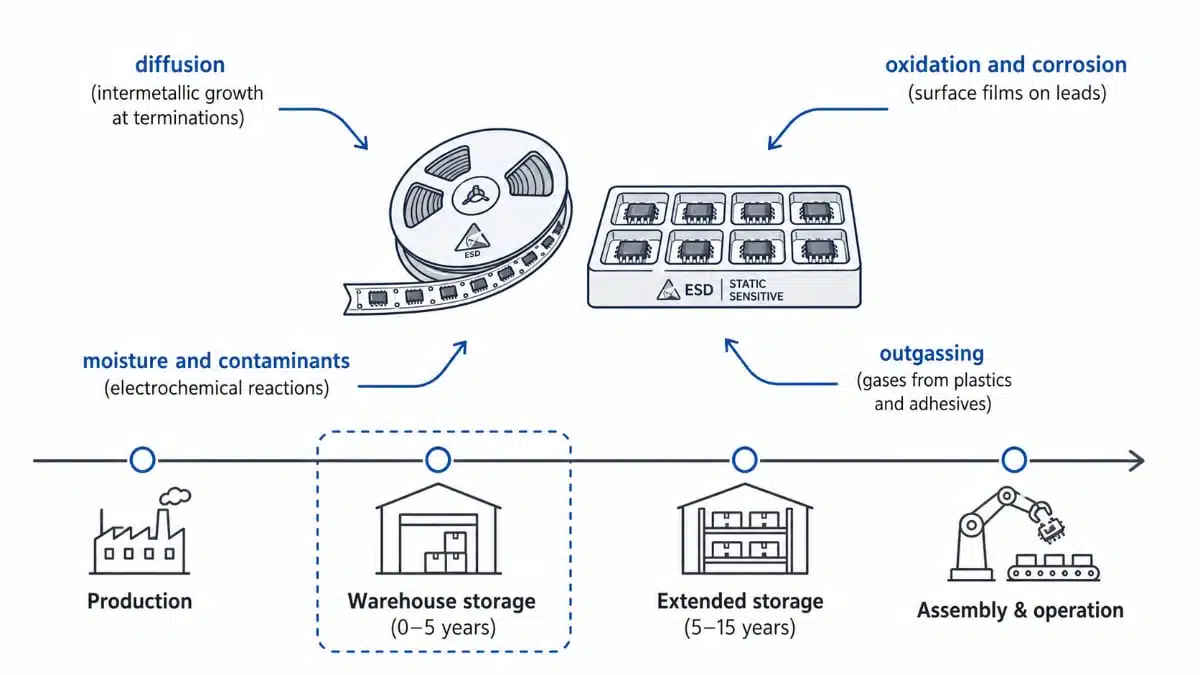
Electronic components are often treated as static building blocks once sealed in bags and placed on warehouse shelves. In reality, they remain physically and chemically active, even when powered off, and continue to age throughout storage. For high‑reliability sectors such as aerospace, defense, medical, and industrial automation, understanding these storage‑related degradation mechanisms is crucial for obsolescence management, spare‑parts strategies, and long‑term reliability.
This article summarizes the main mechanisms that drive aging in stored electronic components, explains why traditional storage measures are not sufficient on their own, and outlines what design, quality and purchasing teams should consider when planning long‑term availability of critical passive and active parts.
Why stored components still age
Even under controlled storage conditions, components are subject to chemical reactions, atomic diffusion and material interactions that slowly change their internal and external structure over time. These changes may not be visible in incoming inspection but can significantly affect solderability, electrical performance and mechanical robustness once the component is assembled and placed into service.
For applications with long life cycles, every batch that goes into storage is a potential risk if its future behavior is not understood and periodically verified. This is especially true when last‑time buys are used to secure supply for legacy platforms over a decade or more.
Main storage‑related degradation mechanisms
The table below summarizes the key mechanisms that drive aging during long‑term storage and their practical impact on components and assemblies.
| Degradation mechanism | Main physical effect during storage | Typical symptoms at use time |
|---|---|---|
| Diffusion | Growth of intermetallic phases at metal interfaces | Poor solderability, brittle joints, increased resistance |
| Oxidation/corrosion | Formation of oxide layers and corrosion products on surfaces | Reduced wetting, higher contact resistance, opens/shorts |
| Outgassing | Release of gases from plastics, adhesives and coatings | Surface contamination, internal corrosion, latent defects |
| Moisture/contaminants | Electrochemical and chemical reactions promoted by humidity | Leakage paths, dendrites, encapsulation damage |
| Tin whiskers/pest | Filament growth or phase change in tin finishes | Sudden shorts, cracked or weakened finishes |
| Material interactions | Reactions between different materials in assemblies or modules | Brightness loss, color shift, pixel or function failures |
This overview shows why long‑term storage must be treated as a multi‑factor problem that cannot be solved by controlling a single parameter such as humidity alone.
Diffusion – slow but relentless structural change
One of the most critical long‑term degradation mechanisms is atomic diffusion, that is, the slow migration of atoms between neighboring materials such as copper and tin in terminations or metallization stacks. Over time, diffusion leads to the growth of intermetallic phases that change the microstructure at interfaces that are essential for solder joints or internal connections.
These intermetallic layers may initially improve wetting, but as they continue to grow they can become brittle, increase contact resistance and ultimately degrade solderability and mechanical integrity. From a practical standpoint, this means that components that have been stored for years may pass visual inspection yet exhibit poor solder wetting, increased voiding or early joint failure during qualification or in the field.
Oxidation and corrosion – surface degradation never stops
Even in well‑controlled storage environments, residual oxygen and moisture are almost impossible to eliminate completely. As a result, metal surfaces on leads, terminations and exposed pads slowly form oxide layers, and under certain conditions corrosion processes take place that reduce solderability and electrical performance.
Traditional protective measures such as dry cabinets or nitrogen cabinets slow down these reactions but do not stop them entirely. For users of passive components with tin, nickel or silver terminations this can translate into increasing contact resistance or intermittent connections in low‑level signal paths due to surface films, as well as reduced solder wetting and longer time‑to‑wet in assembly.
Outgassing – internal materials as hidden sources of degradation
Modern electronic components are complex stacks of plastics, adhesives, coatings and additives that are optimized for electrical and mechanical performance but not necessarily for decades of static storage. Over time these organic materials can release gases, a process known as outgassing, which may include corrosive species, organic vapors and residual solvents.
In a closed storage volume these gases can accumulate and interact with metal surfaces, encapsulations and neighboring components, effectively accelerating degradation from within the package or shipping container. This internal source of contamination is often underestimated because it does not depend on external ambient contamination alone; even “clean” warehouses can suffer from internally generated corrosive atmospheres.
Moisture and environmental contaminants
Humidity and airborne contaminants remain among the most influential drivers of corrosion and chemical degradation in storage. Even relatively low moisture levels can promote electrochemical reactions when combined with ionic residues from manufacturing or sulfur and chlorine compounds from the environment.
These effects can damage encapsulations and interfaces, in extreme cases leading to cracking, delamination or increased leakage currents. They can also corrode terminations and bond pads, especially in fine‑pitch and high‑density assemblies where creepage distances are short, and increase the risk of dendrite growth and intermittent shorts.
Critical phenomena: tin whiskers and tin pest
Two specific phenomena associated with tin and tin‑rich finishes can lead to catastrophic, sudden failures if they develop during storage: tin whiskers and tin pest. Tin whiskers are microscopic conductive filaments that can grow spontaneously from tin surfaces under mechanical or thermomechanical stress and bridge adjacent conductors.
Tin pest refers to a structural transformation of tin at low temperatures that weakens materials and can cause cracking or disintegration of finishes over very long timescales. In safety‑critical systems, avoiding susceptible finishes or applying proven mitigation measures becomes a key part of storage planning and component selection.
Material interactions in displays and complex assemblies
In subsystems such as displays or sensor modules, aging during storage becomes more complex because many different materials are in close proximity and interact over time. Adhesives, sealants and optical materials can release gases or degrade in ways that directly affect optical and electrical properties.
Displays stored for long periods, for example, may suffer loss of brightness, color shifts and pixel defects that only become visible during operation, even though the unit appeared visually intact in storage. From a component engineering perspective, this underscores the need for not only part‑level storage specifications but also system‑level evaluations when assemblies as a whole are stored as spares or for delayed deployment.
Functional degradation in stored assemblies
When complete assemblies, boards or modules are stored, system‑level interactions add another layer of risk beyond individual component behavior. Capacitors are a typical example: over time they can exhibit increased leakage current, changes in capacitance or dielectric degradation, depending on technology and storage conditions.
In combination with residual process contaminants and environmental exposure, such changes can lead to drifting operating points in analog front‑ends or filters and increased power losses and heating in power stages. In worst cases, a set of aged components can interact unfavorably and lead to complete system‑level failure.
The following table gives a qualitative view of how different component categories react to long‑term storage and which failure modes are most relevant from a practical standpoint.
Table: Storage sensitivity of typical component categories
| Component category | Sensitivity in long‑term storage | Dominant storage‑related risks |
|---|---|---|
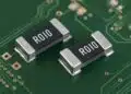
| SMD resistors | Low to medium | Oxidation of terminations, solderability issues |
| MLCCs and ceramic capacitors | Medium | Termination corrosion, cracking due to handling after long storage |
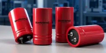
| Aluminum Wet Electrolytic capacitors | High | Increased leakage, capacitance drift, electrolyte drying or aging |
| Film and paper capacitors | Medium | Dielectric aging, contact corrosion, moisture ingress |
| Inductors and transformers | Medium | Core corrosion, insulation aging, solder joint degradation |
| Connectors and relays | High | Contact oxidation, fretting corrosion, increased contact resistance |
| Displays and modules | High | Optical degradation, adhesive outgassing, internal corrosion |
This table can help design and procurement teams prioritize which stored parts are most critical to monitor and re‑qualify over time.
Implications for obsolescence management and supply chain
From a business perspective, storage‑related aging mechanisms translate directly into strategic risk. Component aging can cause production delays, shortages of usable spare parts, costly redesigns when old stock can no longer be qualified, and increased warranty exposure if degraded components enter the field.
For organizations relying on long‑term availability of specific passive or active components, this makes long‑term storage not just a logistics topic but a cross‑functional concern for design engineering, quality, purchasing and obsolescence management. Long‑term storage strategies should therefore be defined early, ideally at design phase, rather than added as an afterthought once a product is discontinued.
Why single‑parameter solutions fall short
Electronic component aging is driven by a combination of diffusion, oxidation, contamination, moisture, material interactions and specific phenomena such as tin whiskers and tin pest. No single parameter such as “keep it dry” or “keep it cool” is sufficient to fully arrest these mechanisms over long time spans.
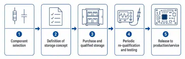
Effective long‑term storage strategies therefore need to address all relevant degradation mechanisms simultaneously, including atmosphere control, material compatibility and mechanical stress. They should also include periodic verification, for example solderability tests, electrical tests and, where necessary, destructive analysis on representative samples.
The next table summarizes typical control measures and which degradation mechanisms they primarily address.
Table: Example long‑term storage control measures
| Control measure | Main mechanisms mitigated | Notes for implementation |
|---|---|---|
| Controlled low humidity (dry cabinet, desiccants) | Moisture, electrochemical corrosion | Requires monitoring and periodic desiccant replacement |
| Inert atmosphere (nitrogen, noble gases) | Oxidation, corrosion, contamination | Reduces oxygen content but does not remove outgassing |
| Temperature control (cool storage, limited cycling) | Diffusion, tin pest, stress effects | Lower temperature slows many reactions but not all |
| Clean handling and packaging (low‑outgassing materials) | Contamination, outgassing | Choice of bags, foams, labels and tapes is critical |
| Periodic re‑qualification and testing | All mechanisms (detection) | Solderability, electrical tests, visual and analytic work |
By mapping measures to mechanisms, storage concepts can be designed more systematically instead of relying on generic “warehouse rules.”
Design‑in notes for engineers
While storage is often seen as a logistics topic, design engineers can significantly influence how well components tolerate long‑term storage by their choices at design time and in component selection. Practical considerations include:
- Prefer component technologies and finishes with known robustness against corrosion and whisker growth when long‑term storage is expected, and review finish options in the manufacturer’s datasheet when available.
- Evaluate whether critical functions rely on parameters that are particularly sensitive to aging, such as leakage current in bias networks or precise capacitance in timing circuits, and consider derating or alternative topologies.
- Coordinate with component engineering and purchasing teams to ensure that storage conditions, shelf‑life expectations and test strategies are captured in the component specification and sourcing documentation.
- For assemblies that will be stored as spares, plan for re‑qualification steps (for example, solderability checks, functional tests or limited burn‑in) and document them in maintenance procedures.
- Where necessary, refer to the manufacturer’s datasheet and application notes for explicit limits on storage time, recommended environmental conditions and any special handling steps after extended storage according to the manufacturer datasheet.
Source
This article is based on information provided by ALTER Technology’s long‑term storage resources on aging mechanisms in electronic components during storage and on related guidance for long‑term conservation and reliability control.