






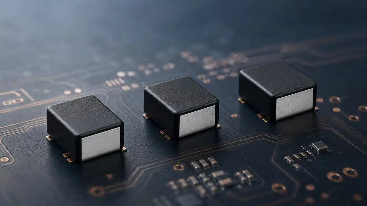
Bourns has introduced three new automotive grade shielded power inductor series designed for high‑density DC‑DC converter designs in harsh environments.
The SRP2010PA, SRP2510PA, and SRP2512PA shielded power inductor series combine metal alloy powder cores, low profiles and AEC‑Q200 qualification, making them attractive options for space‑constrained automotive and miniature electronic systems.
Key features and benefits
- Automotive AEC‑Q200 compliant – suitable for use in automotive ECUs and other in‑vehicle electronics without requiring custom qualification on the basic inductor construction.
- Shielded construction – reduces stray magnetic field radiation, helping designers meet EMC targets and allowing tighter placement of adjacent components such as sensors, small signal ICs or high‑speed data lines.
- Metal alloy powder core – provides soft saturation behavior and high saturation current, improving tolerance to current transients and peak loads in switching regulators.
- High saturation currents up to 9 A – supports point‑of‑load converters and battery‑powered subsystems with substantial peak current demands relative to the inductor footprint.
- Very low profile packages (1.0–1.2 mm height class) – enables use on densely packed multilayer automotive PCBs, including modules with limited z‑height such as camera modules or compact control units.
- Wide operating temperature range from -40 to +145 °C – covers typical automotive mission profiles and under‑hood or near‑powertrain locations where hot‑spot temperatures can be significantly above ambient.
- RoHS compliant and halogen free – supports design‑for‑environment requirements and simplifies global supply for automotive Tier‑1s and OEMs.
Typical applications
The new SRP‑PA series is aimed at compact automotive and miniature electronics where both board area and profile are constrained.
- Automotive DC‑DC converters for 12 V and 48 V systems (point‑of‑load regulators on ECUs, sensor modules and ADAS electronics).
- Power stages in body control modules, lighting control, infotainment and telematics units where EMC and thermal headroom are critical.
- Power rails in camera, radar and lidar modules, where low component height and field containment support tight opto‑mechanical integration.
- DC‑DC stages in miniature electronic devices such as wearables or portable instruments that benefit from automotive‑grade robustness.
Size and current capability overview
The three series mainly differ in footprint, height and available current handling, giving designers several trade‑off points between area and performance.
| Series | Size (L × W × H, mm) | Inductance range (µH) | Heating current Irms (A) | Saturation current Isat (A) | Operating temperature (°C) |
|---|---|---|---|---|---|
| SRP2010PA | 2.0 × 1.6 × 1.0 | 0.1 – 2.2 | 2.2 – 6.6 | 2.4 – 9.0 | -40 to +145 |
| SRP2510PA | 2.5 × 2.0 × 1.0 | 0.22 – 3.3 | 1.9 – 6.3 | 2.5 – 9.0 | -40 to +145 |
| SRP2512PA | 2.5 × 2.0 × 1.2 | 0.22 – 3.3 | 2.1 – 8.5 | 2.8 – 9.0 | -40 to +145 |
Inductance, current ratings and detailed electrical parameters for specific part numbers are according to the official manufacturer datasheet.
Technical highlights
Construction and core material
The SRP‑PA family uses a shielded construction combined with a metal alloy powder core. In practice this means the magnetic path is mostly contained within the component body, and the external field is significantly lower compared to unshielded wirewound inductors of similar size. For switching regulator layouts, this simplifies meeting conducted and radiated emissions targets and reduces coupling into nearby sensitive traces.
Metal alloy powder cores typically exhibit lower core losses at high switching frequencies than traditional ferrite in the same footprint for a given flux swing, especially where ripple current is relatively high. They also tend to show more gradual saturation characteristics, so the inductance does not collapse abruptly with increasing current, providing extra robustness against current spikes.
Current ratings and thermal behavior
Two current figures are specified for each inductor family: a heating current Irms and a saturation current Isat. The heating current is the RMS current level that causes a specified temperature rise, often on the order of 40 °C above ambient under standardized test conditions. The saturation current is linked to the point where inductance drops by a specified percentage, which is key to maintaining energy storage and limiting ripple.
In the SRP‑PA series, saturation currents reach up to 9 A depending on inductance value and package size, making these parts suitable for low‑voltage, high‑current rails such as processor cores, FPGA supplies or high‑speed transceivers on automotive boards. The operating temperature range from -40 to +145 °C ensures that specified performance envelopes remain valid across typical cold‑crank to hot‑soak conditions, provided the thermal design of the PCB and enclosure is adequate.
Form factor and PCB integration
The SRP2010PA series offers the smallest footprint at 2.0 × 1.6 × 1.0 mm, targeting very compact circuits where board real estate is at a premium. The SRP2510PA and SRP2512PA increase board area slightly to 2.5 × 2.0 mm, but with the SRP2512PA adding height to 1.2 mm in exchange for higher heating currents and improved current handling.
From a layout perspective, these low‑profile inductors are well suited to placement under shielding cans or near tall connectors and heatsinks, allowing more efficient use of vertical space. The shielded structure further reduces risk when routing high‑speed differential pairs or RF traces nearby.
Series comparison for selection
For preliminary design‑in, the following simplified view can help narrow down which family might fit best:
| Design priority | Suggested series |
|---|---|
| Minimum footprint and height | SRP2010PA |
| Balance of size and higher Lmax | SRP2510PA |
| Higher Irms in same footprint | SRP2512PA |
Final selection should always be confirmed against converter requirements, loss calculations and thermal measurements under realistic operating conditions.
Design‑in notes for engineers
- Match inductance to converter topology
For typical synchronous buck converters in the few MHz range, inductance in the vicinity covered by these series (sub‑µH to a few µH) is common. The lower end of the range is suitable for high‑current, high‑frequency rails, while the higher values can ease ripple at the expense of transient speed. - Check both Irms and Isat at maximum temperature
In automotive environments, worst‑case inductor temperature can approach the upper operating limit. When using parts up to 145 °C, derate both heating current and saturation current values according to datasheet curves and account for self‑heating plus ambient conditions inside the module. - Consider EMI early in the layout
The shielded construction helps, but return current paths, loop areas and placement relative to input and output capacitors remain critical for low noise performance. Keeping the switch node loop tight and placing the inductor close to the power stage minimizes radiated and conducted emissions. - Evaluate DC resistance and efficiency
At several amps of load current, a few milliohms of difference in DC resistance can translate directly into measurable conduction losses. When comparing devices with similar inductance and size, quantify the impact on total converter efficiency and hotspot temperature. - Use the footprint and height strategically
In multilayer automotive PCBs, local mechanical constraints such as connector keep‑out areas or housing ribs often define where low‑profile components are necessary. The availability of both 1.0 mm and 1.2 mm height families at the same 2.5 × 2.0 mm footprint allows easy trade‑offs if more current handling is needed later. - Plan for lifecycle and supply chain
Since these inductors are automotive grade and AEC‑Q200 qualified, they are intended for long‑term production use. For platform designs, it can be useful to standardize on one or two footprint families (for example SRP2510PA/SRP2512PA) to improve flexibility and second‑source strategies within the same manufacturer.
Source
This article is based on information provided in the official Bourns new product release and related technical documentation for the SRP2010PA, SRP2510PA, and SRP2512PA shielded power inductor series.