











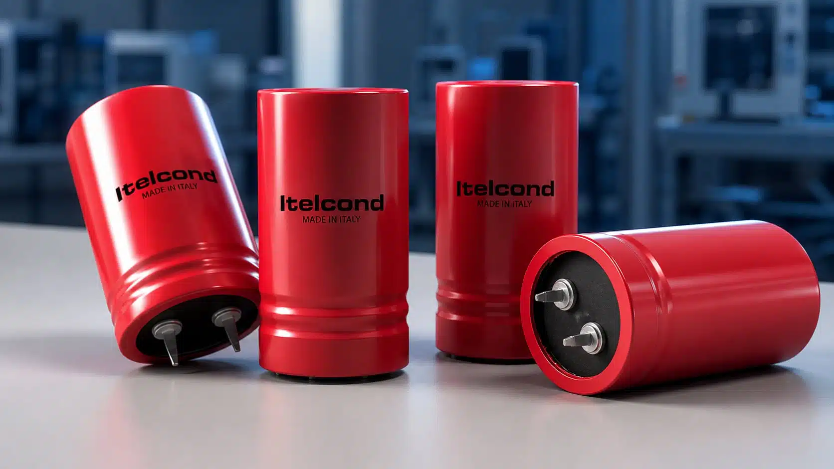
Itelcond has introduced new high‑voltage aluminium electrolytic capacitor series AM and AN aimed at DC‑link applications tracking the latest increase in IGBT module voltage ratings.
These Itelcond aluminium electrolytic capacitors push the DC working voltage range up to 500–550 V while keeping the same case dimensions as existing low‑ESR series, which simplifies drop‑in upgrades of established power designs. According to the manufacturer datasheet they combine long lifetime, high ripple current capability and robust mechanical options for demanding industrial, renewable and e‑mobility systems.
Key features and benefits
- Higher DC voltage rating in same can size – AM and AN parts are specified for 500–550 V DC operation, approximately 100 V higher than previous Itelcond low‑ESR generations with comparable dimensions, enabling migration from 1.2 kV to higher‑voltage IGBT stacks without redesigning the capacitor bank footprint.
- Application‑oriented series split – AM targets general high‑voltage DC‑link use with a 5 000 h life rating at 105 °C, while AN extends lifetime to 15 000 h at 85 °C for applications where ambient temperature can be managed but long field life is critical.
- Multiple mounting styles – The family covers classic screw‑terminal cans (AM and AN) and AMC / AMS snap‑in versions with 2–4 pins, giving designers a consistent platform from PCB‑mounted power supplies up to large cabinet‑level inverters.
- Wide mechanical size range – Available diameters run from 30 mm to 90 mm with heights from 40 mm to 240 mm depending on series, so designers can optimize between compact single cans and parallel banks for higher ripple current or lower ESR.
- High operating temperature – AM and AMC / AMS snap‑ins are rated for continuous operation up to 105 °C, allowing tighter placement near heatsinks or inductors in dense power stages; AN devices trade a lower 85 °C rating for extended lifetime.
- Long service life – Typical endurance figures are 5 000 h for AM and AMC / AMS at 105 °C and 15 000 h for AN at 85 °C, with lifetime extension available through standard voltage and temperature derating per Itelcond’s general data book guidance.
- Designed for demanding ripple conditions – The AM / AN platform is derived from Itelcond’s low‑ESR and high‑ripple screw‑terminal technology used in existing AY‑HR and AD series, so DC‑link designers can expect low internal heating and good stability over load cycling according to manufacturer data.
- Compliance with industrial standards – Itelcond specifies alignment with IEC and CECC climatic categories and safety practices for aluminium electrolytics across its screw‑terminal portfolio, simplifying qualification for industrial and transportation equipment.
Typical applications
The AM and AN series are positioned for high‑performance power conversion where DC‑link voltage is moving towards the upper end of 1 700 V IGBT and similar platforms. Example application domains called out by the manufacturer include solar and wind power inverters, UPS systems, EV chargers and industrial energy storage.
- Green energy and grid‑tied inverters
- Solar central and string inverters with 1 000–1 500 V DC inputs.
- Wind turbine converters and pitch control drives requiring compact, long‑life DC‑link capacitors.
- Industrial and infrastructure power
- Large UPS installations and power filters where 500–550 V capacitors reduce series string count in the DC bus.
- High‑power industrial drives and welders using high‑voltage IGBT or SiC modules.
- Automotive and e‑mobility
- Off‑board EV DC fast chargers with increased output voltages for heavy‑duty or 800 V battery systems.
- Auxiliary inverters and DC‑link stages in charging infrastructure cabinets.
- Energy storage systems
- Battery‑buffered storage with high‑voltage DC racks, where long capacitor life and screw‑terminal robustness are important for serviceability.
In many of these designs, the 500–550 V rating allows using a single capacitor string per DC pole instead of series‑connecting lower‑voltage cans, which improves energy density and reduces balancing resistor losses as described in Itelcond’s general design notes.
Technical highlights
According to the Itelcond datasheet, the AM / AN series are optimised for operation directly across DC bus voltages in the 500–550 V range associated with higher‑voltage IGBT modules. The series share common electro‑mechanical technology with other Itelcond screw‑terminal and snap‑in families; detailed electrical characteristics such as ESR, ripple current ratings and exact capacitance spreads are defined per part number in the manufacturer datasheet rather than in the brief press release.
Series overview
| Series | Terminal type | Life time (hrs) | Max temp (°C) | Voltage range (V DC) | Typical case sizes (mm, D×H) | Notes |
|---|---|---|---|---|---|---|
| AM | Screw | 5 000 | 105 | 500–550 | 51×80 to 90×240 | High‑voltage DC‑link, 105 °C endurance according to datasheet. |
| AMC / AMS | Snap‑in 2–4 pins | 5 000 | 105 | 500–550 | 30×40 to 50×105 | PCB‑mount versions aligned with AM electrical ratings. |
| AN | Screw | 15 000 | 85 | 500–550 | 51×80 to 90×240 | Extended life series for controlled ambient temperatures. |
The life test conditions for these series follow Itelcond’s standard aluminium electrolytic practice: endurance is specified at rated voltage, rated ripple and the upper category temperature, with capacitance drift, ESR and leakage limits defined by IEC‑style criteria. In practice, operating at lower case temperature or applying voltage derating can significantly extend expected lifetime as illustrated in the generic life‑calculation graphs of the Itelcond data book.
The AM and AN families are indicated as “low ESR solutions” relative to conventional high‑voltage electrolytics, which translates into lower internal power loss under ripple current and helps keep hot‑spot temperature within life‑calculation assumptions. As usual for screw‑terminal capacitors in this class, peak surge and transient over‑voltage limits, leakage current and ripple multipliers versus temperature and frequency are specified per series and must be observed for reliable service.
Design‑in notes for engineers
- Match capacitor voltage to IGBT stack headroom
- For a three‑phase inverter with a 1 000–1 200 V DC bus previously using 400–450 V electrolytics in series, AM / AN at 500–550 V can reduce the series count or increase margin against regenerative and transient peaks.
- Follow Itelcond’s guidance that the sum of DC bus voltage and ripple must not exceed the rated working voltage, and reserve headroom for surge and transient conditions defined in the datasheet.
- Use life‑calculation tools, not only nameplate hours
- The 5 000 h at 105 °C or 15 000 h at 85 °C are endurance test points; actual field life can be much longer when the hot‑spot temperature stays well below these limits.
- Itelcond’s data book describes useful‑life estimation based on ripple current ratio and case temperature, and shows that derating voltage to about 80% of rated gives most of the benefit without excessive oversizing.
- Consider mounting style early in the mechanical concept
- Screw‑terminal AM and AN cans suit rack‑level busbar assemblies and allow straightforward series / parallel banks with low inductance when combined with laminated busbars.
- AMC / AMS snap‑ins simplify assembly in compact power supplies but need careful PCB copper spreading and thermal vias to manage ripple heating; layout must also respect creepage and clearance for 500–550 V DC plus transients.
- Plan for inrush, fault and balancing behaviour
- At these voltage levels, inrush current into the DC link and energy during short circuits become significant; soft‑start circuits and properly rated discharge resistors are recommended.
- If lower‑voltage cans are still used in series in some parts of the design, Itelcond provides formulas and examples for calculating balancing resistors based on leakage current deviation, which remain relevant for mixed banks.
- Thermal management and placement
- Aluminium electrolytics age primarily with core temperature, not ambient alone; proximity to hot IGBTs, chokes or braking resistors should be avoided, or compensated by airflow and case‑temperature monitoring.
- In outdoor renewable or EV‑charging cabinets, consider that top‑of‑cabinet locations can see higher ambient, so specifying AN for cooler sections and AM for hotter drive bays can balance cost and life.
- Reliability and safety aspects
- Itelcond specifies FIT‑rate‑based reliability models and notes the presence of safety vents operating around 7.5 bar internal pressure, which influence enclosure venting needs at high altitude or in sealed cabinets.
- As with all large electrolytics, charge retention due to dielectric absorption means that DC‑link capacitors may self‑re‑charge to tens of volts after disconnection; service procedures should always include verified discharge before touch.
Source
This article is based on an official press release and catalogue information from Itelcond describing the AM / AN high‑voltage aluminium electrolytic capacitor series and related screw‑terminal and snap‑in product families, complemented by general design guidance from the company’s aluminium electrolytic data book.












