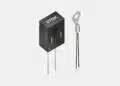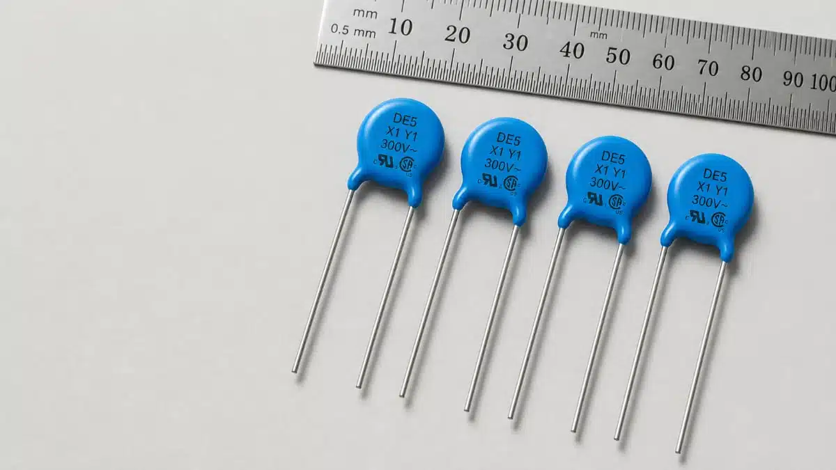
Murata’s new DE5 series introduces automotive safety-certified lead-type disc ceramic capacitors with X1/Y1 class approval for use directly on AC mains and high-voltage automotive systems.
These Murata lead-type disc ceramic capacitors extend the voltage and impulse margins beyond the existing DE6 family, giving design engineers more headroom for noise suppression and insulation coordination in demanding on‑board charger and industrial applications.
Key features and benefits
- X1/Y1 safety-class approval for mains-connected use
The DE5 series is certified to the X1/Y1 subclass defined in IEC 60384‑14, covering capacitors connected directly to commercial AC power lines with the most stringent requirements on insulation, impulse voltage and flame-retardant performance. - Higher AC mains rating than DE6 series
While the established DE6 safety capacitors target Y2 class at 300 Vac (r.m.s.), DE5 parts are specified up to 500 Vac (r.m.s.) Y1 class and 760 Vac (r.m.s.) X1 rating according to the manufacturer’s datasheet, allowing direct use on higher-voltage lines and in topologies with significant overvoltage stress. - 12 kV impulse withstand voltage for additional safety margin
The impulse test level is raised from 5 kV in typical Y2 designs to 12 kV for DE5, providing extra robustness against lightning surges, switching transients and insulation test requirements in EV and industrial environments. - Automotive-grade qualification (AEC‑Q200)
The series is compliant with AEC‑Q200 Rev. E, making it suitable for automotive ECUs and on‑board chargers where temperature cycling, mechanical shock, vibration and long‑term reliability are critical. - Broad capacitance range for EMI filter flexibility
Initial lineup covers nominal capacitances from 100 pF up to 4.7 nF across B and E temperature characteristics, enabling fine tuning of common-mode and differential-mode noise attenuation in input filters. - Compact disc form factor with defined lead spacing
Lead spacing of 10 mm with disc diameters from approximately 6 mm to 14 mm max simplifies PCB layout in tight input filter areas, while providing sufficient creepage and clearance when combined with appropriate board design. - Lead-type construction for creepage and mechanical robustness
Radial leads and disc geometry support stable positioning, predictable creepage distances across the ceramic body, and ease of insertion for through-hole assembly or selective soldering.
Typical applications
Safety-certified X/Y capacitors like the DE5 series are used wherever suppression of mains-borne noise must be combined with controlled failure modes and defined insulation behavior.
- EV on-board chargers (OBCs)
- Input EMI filters between the AC grid and PFC stage
- Common-mode noise suppression between line and protective earth at elevated OBC voltages
- Designs requiring Y1 rather than Y2 due to higher surge or margin targets
- Automotive power electronics and ECUs
- High-voltage DC/AC interfaces in hybrid and battery electric platforms
- Auxiliary power modules and DC/DC converters connected to AC charging infrastructure
- Safety-related control units needing certified mains coupling capacitors
- Industrial power supplies and drives
- Three-phase and single-phase input filters for converters with nominal mains up to 500 Vac
- Noise suppression in motor drives, welders and high‑power SMPS with strict safety compliance requirements.
- General EMI suppression on AC mains
- X1 positions (line‑to‑line) in environments with higher impulse stress
- Y1 positions (line‑to‑earth) where insulation coordination demands more headroom than conventional Y2 designs.
Technical highlights
Safety class and standards
- X1/Y1 subclass according to IEC 60384‑14, covering:
- Higher impulse test voltages than Y2 class
- Flame-retardant performance suitable for direct mains connection
- Designed for use on commercial AC power lines, with failure behavior controlled to minimize risk of fire or electric shock due to leakage current.
Electrical ratings
- Capacitance values (initial lineup):
- 100 pF, 150 pF, 220 pF, 330 pF, 470 pF, 680 pF
- 1,000 pF, 1,500 pF, 2,200 pF, 3,300 pF, 4,700 pF
- Temperature characteristics:
- B characteristic for lower capacitance values
- E characteristic for higher capacitances as specified in the manufacturer’s table
- Rated voltages:
- 1,500 Vdc
- 760 Vac (r.m.s.) X1 rating
- 500 Vac (r.m.s.) Y1 rating
- Impulse withstand voltage:
- 12 kV test voltage according to the manufacturer’s specification.
In practice, the combination of 500 Vac Y1 and 12 kV impulse capability makes these parts suitable for grids with higher nominal voltage and installations where surge levels or test regimes exceed typical Y2 requirements.
Specifications
A simplified overview of the initial DE5 series part numbers and key mechanical parameters is given below; for precise values, refer to the manufacturer’s datasheet.
| Part number | Capacitance | Temp. char. | Lead spacing | Max. disc diameter | Qualification |
|---|---|---|---|---|---|
| DE5B3RB101K**R01F | 100 pF | B | 10 mm | 6.0 mm | AEC‑Q200 Rev. E |
| DE5B3RB151K**R01F | 150 pF | B | 10 mm | 8.0 mm | AEC‑Q200 Rev. E |
| DE5B3RB221K**R01F | 220 pF | B | 10 mm | 6.0 mm | AEC‑Q200 Rev. E |
| DE5B3RB331K**R01F | 330 pF | B | 10 mm | 7.0 mm | AEC‑Q200 Rev. E |
| DE5B3RB471K**R01F | 470 pF | B | 10 mm | 8.0 mm | AEC‑Q200 Rev. E |
| DE5B3RB681K**R01F | 680 pF | B | 10 mm | 9.0 mm | AEC‑Q200 Rev. E |
| DE5E3RB102M**R01F | 1,000 pF | E | 10 mm | 8.0 mm | AEC‑Q200 Rev. E |
| DE5E3RB152M**R01F | 1,500 pF | E | 10 mm | 9.0 mm | AEC‑Q200 Rev. E |
| DE5E3RB222M**R01F | 2,200 pF | E | 10 mm | 11.0 mm | AEC‑Q200 Rev. E |
| DE5E3RB332M**R01F | 3,300 pF | E | 10 mm | 13.0 mm | AEC‑Q200 Rev. E |
| DE5E3RB472M**R01F | 4,700 pF | E | 10 mm | 14.0 mm | AEC‑Q200 Rev. E |
The “***” in the part number denotes internal Murata code options; exact suffix meanings (packing, lead style, etc.) should be confirmed in the detailed product documentation.
Design‑in notes for engineers
Selecting between Y2 and Y1 solutions
- Assess impulse and insulation requirements early
If your requirements or internal standards mandate impulse test levels above 5 kV or mains voltage ratings above 300 Vac (r.m.s.), Y1‑class components like DE5 should be considered instead of Y2‑only alternatives. - Check grid voltage and OBC architecture
For EV on‑board chargers connected to higher nominal mains or operating with wide-range universal input, verify that line‑to‑earth capacitors meet both the continuous voltage rating and the surge profile from standards and OEM specifications. - Coordinate with insulation design
Safety capacitors form part of the overall insulation system. Ensure that creepage/clearance distances on the PCB, connector choices and enclosure design are aligned with the higher Y1 class requirements to take full advantage of the DE5 series capabilities.
Practical layout and EMC considerations
- Respect creepage and clearance distances around the disc
Although DE5 parts offer 10 mm lead spacing and defined disc diameters, PCB layout must maintain creepage and clearance according to the applied standards (IEC 60664, OEM rules). Avoid copper pours, silkscreen or mechanical parts that reduce effective distances. - Place X and Y capacitors close to the EMI filter entry point
For best common‑mode and differential‑mode attenuation, position DE5 capacitors close to the AC inlet or connector, with low‑inductance connections to line and earth nodes. Minimize loop area to improve high‑frequency performance. - Consider temperature characteristics in wide‑range applications
B and E temperature characteristics influence capacitance stability over temperature. For applications with large ambient swings or internal heating, evaluate whether the selected characteristic maintains sufficient capacitance at the extremes specified in the datasheet. - Validate surge and stress in real operation
Run surge tests and power cycling that reflect real‑world AC grids, lightning exposure and switching transients. Even with 12 kV impulse rating, system‑level interactions (cable length, EMC components, protection devices) can alter stress distribution.
Purchasing and qualification hints
- Use AEC‑Q200 status to streamline automotive approvals
The AEC‑Q200 Rev. E compliance of DE5 capacitors simplifies qualification for automotive platforms, but OEM‑specific component approval processes should still be followed. - Pair DE5 and DE6 series where appropriate
Legacy designs using DE6 Y2 components at lower mains ratings can coexist with DE5 Y1 parts in new platforms, providing a clear migration path while keeping the supplier base and technology uniform. - Rely on official datasheets for exact limits
For parameters such as permissible operating temperature range, derating curves, capacitance tolerances and endurance test conditions, refer directly to the manufacturer datasheet rather than assuming generic X/Y capacitor behavior.
Source
This article is based on information provided in Murata’s official product and event news release for the DE5 series of automotive safety-certified lead-type disc ceramic capacitors, complemented by the associated manufacturer product documentation.