Passive Components Blog
No Result
View All Result
  • Home
  • NewsFilter
    • All
    • Aerospace & Defence
    • Antenna
    • Applications
    • Automotive
    • Capacitors
    • Circuit Protection Devices
    • electro-mechanical news
    • Filters
    • Fuses
    • Inductors
    • Industrial
    • Integrated Passives
    • inter-connect news
    • Market & Supply Chain
    • Market Insights
    • Medical
    • Modelling and Simulation
    • New Materials & Supply
    • New Technologies
    • Non-linear Passives
    • Oscillators
    • Passive Sensors News
    • Resistors
    • RF & Microwave
    • Telecommunication
    • Weekly Digest

    In the Age of AI, Every Watt Counts: Implications for Components

    Stackpole Extends Resistance Range of 2512 High‑Power Current Sense Resistors

    Wk 27 Electronics Supply Chain Digest

    Littelfuse Announced TVS Diodes for 48 V Automotive Systems

    Spectrum Controls Joins Modelithics Program to Offer High‑Fidelity RF Models for Resistors, Attenuators and Terminations

    RF Filters and Passive Components Enabling the 7 Missile RF Subsystems

    Ferrite versus Nanocrystalline Power Inductor Cores: Turns, Gap and Size

    YAGEO Presents NANOMET Soft Magnetic Cores for High‑Density Power Conversion

    Coilcraft Releases High-Current Ferrite Beads for CISPR 25 EMC compliance

    Trending Tags

    • Ripple Current
    • RF
    • Leakage Current
    • Tantalum vs Ceramic
    • Snubber
    • Low ESR
    • Feedthrough
    • Derating
    • Dielectric Constant
    • New Products
    • Market Reports
  • VideoFilter
    • All
    • Antenna videos
    • Capacitor videos
    • Circuit Protection Video
    • Filter videos
    • Fuse videos
    • Inductor videos
    • Inter-Connect Video
    • Non-linear passives videos
    • Oscillator videos
    • Passive sensors videos
    • Resistor videos

    Ferrite versus Nanocrystalline Power Inductor Cores: Turns, Gap and Size

    KYOCERA AVX Presents Antenna Integrator Studio Tutorial for Antenna Placement and RF Design

    Power Design Simulation Tools for Faster Inductor Selection and Loss Optimization

    EMC‑Compliant PCB and Connector Design Guidelines

    Why Isolated DC/DC Power Supplies Fail Late, Würth Elektronik Podcast

    Designing 800 V DC EMC Filters: Calculation, Simulation and Measurement

    Current Sense Transformer Datasheet and Design‑in Guide

    Designing a USB Type‑C Flyback Planar Transformer with Frenetic’s Planar Tool

    Magnetics Design in High‑Frequency GaN Converters

    Trending Tags

    • Capacitors explained
    • Inductors explained
    • Resistors explained
    • Filters explained
    • Application Video Guidelines
    • EMC
    • New Products
    • Ripple Current
    • Simulation
    • Tantalum vs Ceramic
  • Knowledge Blog
  • Dossiers
    • AI Hardware Dossier
    • Power Converter Dossier
    • Automotive Dossier
    • Capacitor Dossier
    • Resistor Dossier
    • Inductor Dossier
    • Circuit Protection Dossier
  • Suppliers
    • Who is Who
  • PCNS
    • PCNS 2025
    • PCNS 2023
    • PCNS 2021
    • PCNS 2019
    • PCNS 2017
  • Events
  • Home
  • NewsFilter
    • All
    • Aerospace & Defence
    • Antenna
    • Applications
    • Automotive
    • Capacitors
    • Circuit Protection Devices
    • electro-mechanical news
    • Filters
    • Fuses
    • Inductors
    • Industrial
    • Integrated Passives
    • inter-connect news
    • Market & Supply Chain
    • Market Insights
    • Medical
    • Modelling and Simulation
    • New Materials & Supply
    • New Technologies
    • Non-linear Passives
    • Oscillators
    • Passive Sensors News
    • Resistors
    • RF & Microwave
    • Telecommunication
    • Weekly Digest

    In the Age of AI, Every Watt Counts: Implications for Components

    Stackpole Extends Resistance Range of 2512 High‑Power Current Sense Resistors

    Wk 27 Electronics Supply Chain Digest

    Littelfuse Announced TVS Diodes for 48 V Automotive Systems

    Spectrum Controls Joins Modelithics Program to Offer High‑Fidelity RF Models for Resistors, Attenuators and Terminations

    RF Filters and Passive Components Enabling the 7 Missile RF Subsystems

    Ferrite versus Nanocrystalline Power Inductor Cores: Turns, Gap and Size

    YAGEO Presents NANOMET Soft Magnetic Cores for High‑Density Power Conversion

    Coilcraft Releases High-Current Ferrite Beads for CISPR 25 EMC compliance

    Trending Tags

    • Ripple Current
    • RF
    • Leakage Current
    • Tantalum vs Ceramic
    • Snubber
    • Low ESR
    • Feedthrough
    • Derating
    • Dielectric Constant
    • New Products
    • Market Reports
  • VideoFilter
    • All
    • Antenna videos
    • Capacitor videos
    • Circuit Protection Video
    • Filter videos
    • Fuse videos
    • Inductor videos
    • Inter-Connect Video
    • Non-linear passives videos
    • Oscillator videos
    • Passive sensors videos
    • Resistor videos

    Ferrite versus Nanocrystalline Power Inductor Cores: Turns, Gap and Size

    KYOCERA AVX Presents Antenna Integrator Studio Tutorial for Antenna Placement and RF Design

    Power Design Simulation Tools for Faster Inductor Selection and Loss Optimization

    EMC‑Compliant PCB and Connector Design Guidelines

    Why Isolated DC/DC Power Supplies Fail Late, Würth Elektronik Podcast

    Designing 800 V DC EMC Filters: Calculation, Simulation and Measurement

    Current Sense Transformer Datasheet and Design‑in Guide

    Designing a USB Type‑C Flyback Planar Transformer with Frenetic’s Planar Tool

    Magnetics Design in High‑Frequency GaN Converters

    Trending Tags

    • Capacitors explained
    • Inductors explained
    • Resistors explained
    • Filters explained
    • Application Video Guidelines
    • EMC
    • New Products
    • Ripple Current
    • Simulation
    • Tantalum vs Ceramic
  • Knowledge Blog
  • Dossiers
    • AI Hardware Dossier
    • Power Converter Dossier
    • Automotive Dossier
    • Capacitor Dossier
    • Resistor Dossier
    • Inductor Dossier
    • Circuit Protection Dossier
  • Suppliers
    • Who is Who
  • PCNS
    • PCNS 2025
    • PCNS 2023
    • PCNS 2021
    • PCNS 2019
    • PCNS 2017
  • Events
No Result
View All Result
Passive Components Blog
No Result
View All Result

Stackpole Extends Resistance Range of 2512 High‑Power Current Sense Resistors

13.7.2026
Reading Time: 6 mins read
A A

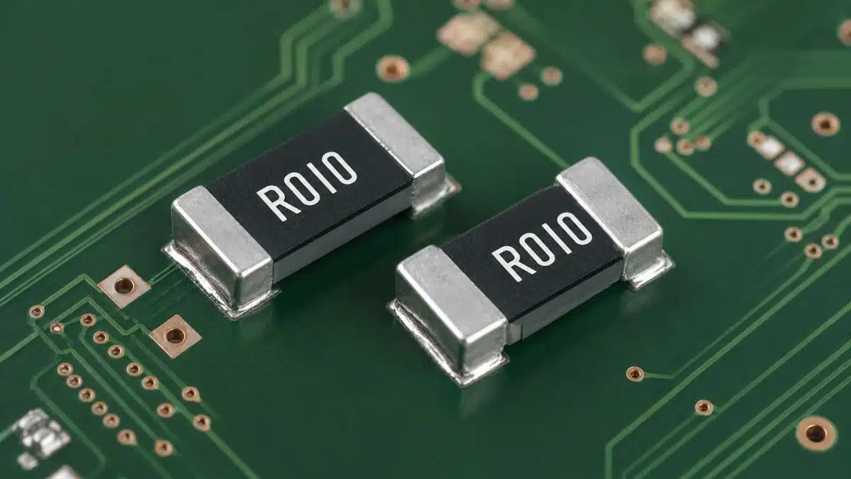
Stackpole Electronics has expanded its CSSU high‑power metal alloy current sense resistor series with new 0.5 mΩ and 20 mΩ values in the familiar 2512 SMD package.

These additions give power electronics designers more flexibility to optimize measurement accuracy, losses, and board space in high‑current circuits.

RelatedPosts

Stackpole Releases High-Frequency Thin Film Chip Resistors for RF up to 50 GHz

Stackpole Introduces 1400A Busbar Shunt Resistors

Stackpole Introduces High‑Voltage Low VCR Chip Resistors

Key features and benefits

  • High power handling in 2512 footprint
    The CSSU series is rated up to 5 W in a standard 2512 surface‑mount package, allowing designers to sense large currents without moving to oversized or custom footprints.
  • Very low resistance option: 0.5 mΩ
    The new 0.5 milliohm value minimizes voltage drop and power dissipation in the shunt, which helps improve overall efficiency in high‑current rails and battery paths.
  • Higher resistance option: 20 mΩ
    The added 20 milliohm value increases the sense voltage for a given current, easing the requirements on measurement circuitry and improving resolution in lower‑current ranges.
  • Metal alloy current sensing technology
    The metal alloy construction is designed for low TCR, stable resistance over time, and robust performance under thermal and mechanical stress typical of power electronics.
  • AEC‑Q200 qualification
    AEC‑Q200 qualification makes the CSSU series suitable for automotive ECUs and other applications where formal reliability and stress testing is required.
  • Support for high power density designs
    Being able to dissipate up to 5 W in a 2512 footprint allows higher power density and can reduce the need for parallel shunts or larger packages.

Typical applications

The CSSU current sense resistor series targets demanding current sensing tasks in modern power and battery systems. Typical uses include:

  • Battery management systems (BMS) in EVs, industrial battery packs and energy storage systems, where accurate shunt measurement is needed for charge and discharge control.
  • Automotive electronics, including ECUs, power distribution modules, on‑board chargers and DC‑DC converters that must meet automotive qualification standards.
  • Motor drives and motion control, where phase and bus current monitoring is essential for protection and control loops.
  • Industrial power supplies and DC‑DC converters, from server and telecom supplies to industrial automation PSUs.
  • Renewable energy equipment such as inverters and charge controllers, where high DC currents and elevated temperatures are common.
  • General high‑current power control systems that need compact, reliable current sensing in the main power path.

Technical highlights

The press release emphasizes the following core technical aspects of the CSSU current sense resistor series:

  • Package size: 2512 SMD footprint, supporting up to 5 W power dissipation according to the manufacturer.
  • Resistance values: Expanded range now includes 0.5 mΩ and 20 mΩ options; additional values are available in the broader CSSU portfolio as per the datasheet.
  • Power rating: 5 W continuous power capability in 2512, enabling design‑ins where significant current and associated heat must be managed.
  • Technology: Metal alloy current sense element designed for low resistance, low TCR and long‑term stability in power electronics environments.
  • Qualification: AEC‑Q200 qualified series, supporting use in automotive and other high‑reliability applications.
  • Stability and robustness: The product family is described as combining low resistance, low TCR and excellent long‑term stability, which is important when shunt value drift would impact current measurement accuracy.

In practice, low resistance values such as 0.5 mΩ are used where the designer wants to minimize measurement losses and voltage drop on the bus, while values like 20 mΩ are often chosen when higher measurement voltage is needed for precise sensing or when operating currents are lower. Exact derating curves, TCR values and resistance range should be taken from the manufacturer’s datasheet.

Example selection table

The following illustrative table shows how the two new resistance values map to typical current ranges and sense voltages. Actual limits and ratings must be verified against the manufacturer datasheet and application conditions.

CSSU valueTypical current range exampleSense voltage behavior (qualitative)Typical use focus
0.5 mΩHigh currents (tens to hundreds of amps, depending on layout and cooling)Very low voltage drop, minimized measurement lossesMain battery bus, high‑current DC link
20 mΩLower to moderate currents where resolution matters more than minimal dropHigher sense voltage for a given currentPrecision sensing, lower‑current rails

Design‑in notes for engineers

  • Define current range and power budget early
    Start by estimating peak and continuous current through the shunt and the allowable voltage drop. Use the CSSU 5 W rating in combination with ambient temperature and PCB thermal design, as documented by the manufacturer, to select a safe value.
  • Choose resistance to balance losses vs. measurement resolution
    Use lower resistance values like 0.5 mΩ for high‑current paths where efficiency and bus voltage integrity are critical. Consider higher values like 20 mΩ when working with lower currents or when the measurement circuitry benefits from a larger sense voltage.
  • Check AEC‑Q200 and application environment
    If the design is automotive or subject to similar stress profiles, take advantage of the AEC‑Q200 qualification and verify that the chosen CSSU variant and mounting meet the requirement profiles for shock, vibration and temperature cycling.
  • Layout for thermal performance and accuracy
    Place the CSSU resistor to allow good copper area for heat spreading, and route Kelvin sense connections (where applicable) to minimize error due to track resistance. Observe manufacturer guidance on pad design and solder fillet to achieve the claimed 5 W performance.
  • Consider measurement front‑end design
    Ensure that the downstream measurement circuitry (op amp or dedicated current sense IC) is designed for the expected sense voltage range and common‑mode voltage. The new 20 mΩ option can help when sense voltage is otherwise too small for robust measurement.
  • Consult datasheet for detailed limits
    For exact resistance range, tolerance, TCR values, pulse handling and derating, refer to the latest CSSU series datasheet and application notes. This is especially important when pushing the component towards the upper end of its power and temperature envelope.

Source

This article is based on information provided in the official Stackpole Electronics press release announcing the expansion of the CSSU high‑power metal alloy current sense resistor series, complemented by general engineering context for current sensing design.

References

  1. Stackpole CSSU series press release – expansion with 0.5 mΩ and 20 mΩ values
  2. Stackpole Electronics official website

Related

Recent Posts

Littelfuse Announced TVS Diodes for 48 V Automotive Systems

10.7.2026
15

Spectrum Controls Joins Modelithics Program to Offer High‑Fidelity RF Models for Resistors, Attenuators and Terminations

10.7.2026
16

Coilcraft Releases High-Current Ferrite Beads for CISPR 25 EMC compliance

8.7.2026
41

Vishay Unveils Multi-Turn Position Sensor for Harsh Industrial Environments

7.7.2026
30

YAGEO Introduces Automotive MOV Surge Protection Varistor

7.7.2026
28

TDK Releases Compact SMD Gate Drive Transformers for xEV

7.7.2026
42

Molex Unveils Automotive Ethernet Connectors for Next‑Gen SDV Architectures

2.7.2026
42

TAIYO YUDEN Introduced Hybrid Aluminum Capacitors for 48V Automotive Power Supplies

2.7.2026
73

YAGEO Announces July 2026 Capacitor Price Increase

1.7.2026
709

Upcoming Events

Jul 14
16:00 - 17:00 CEST

EMC Design Essentials: Mastering Varistors and Common Mode Chokes

Jul 21
16:00 - 17:00 CEST

Safety by design: X and Y Interference suppression capacitors for power line filters

Jul 28
8:00 - 11:00 CEST

Post Procurement Testing of EEE Components for LEO Space Applications

View Calendar

Popular Posts

  • Boost Converter Design and Calculation

    0 shares
    Share 0 Tweet 0
  • Buck Converter Design and Calculation

    0 shares
    Share 0 Tweet 0
  • Flyback Converter Design and Calculation

    0 shares
    Share 0 Tweet 0
  • LLC Resonant Converter Design and Calculation

    0 shares
    Share 0 Tweet 0
  • YAGEO Announces July 2026 Capacitor Price Increase

    0 shares
    Share 0 Tweet 0
  • MLCC and Ceramic Capacitors

    0 shares
    Share 0 Tweet 0
  • Earthing Systems and IEC Classification Explained

    0 shares
    Share 0 Tweet 0
  • Nvidia Vera Rubin: Why One AI Rack Needs So Many More MLCC Capacitors

    0 shares
    Share 0 Tweet 0
  • MLCCs in the Age of AI: Q2 2026 Market Tightness

    0 shares
    Share 0 Tweet 0
  • Dual Active Bridge (DAB) Topology

    0 shares
    Share 0 Tweet 0

Newsletter Subscription


Passive Components Blog

© EPCI - Leading Passive Components Educational and Information Site

  • Home
  • Privacy Policy
  • EPCI Membership & Advertisement
  • About

No Result
View All Result
  • Home
  • Knowledge Blog
  • Dossiers
  • PCNS

© EPCI - Leading Passive Components Educational and Information Site

This website uses cookies. By continuing to use this website you are giving consent to cookies being used. Visit our Privacy and Cookie Policy.
Go to mobile version