


Passive Components Blog
No Result
View All Result
  • Home
  • News
    • All
    • Aerospace & Defence
    • Antenna
    • Applications
    • Automotive
    • Capacitors
    • Circuit Protection Devices
    • electro-mechanical news
    • Filters
    • Fuses
    • Inductors
    • Industrial
    • Integrated Passives
    • inter-connect news
    • Market & Supply Chain
    • Market Insights
    • Medical
    • Modelling and Simulation
    • New Materials & Supply
    • New Technologies
    • Non-linear Passives
    • Optoelectronics and Isolation
    • Oscillators
    • Passive Sensors News
    • Resistors
    • RF & Microwave
    • Telecommunication
    • Weekly Digest
    TDK and TAIYO YUDEN business alliance announcement for advanced MLCCs and inductors supporting AI infrastructure.

    TDK and TAIYO YUDEN Explore Alliance for MLCCs and Inductors

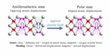
    Antiferroelectric hafnia crystal structure showing alternating polar layers and field-aligned polar state, University of Nebraska–Lincoln

    Antiferroelectric Hafnia at the 2D Limit

    Bourns UALH Series aluminum housed high-power wirewound resistor in a thin rectangular metal enclosure

    Bourns Wirewound Resistors Target 100 W Industrial Designs

    Coilcraft CSX7045 surface-mount current sense transformers with compact chip-style package

    Coilcraft Extends Current Sense Transformers with 1.8 kVrms Isolation

    Metallized film capacitor winding with PEN, PET and polypropylene dielectric film layers shown in a power-electronics supply-chain concept

    PEN Film Supply Challenges and Capacitor Replacement Paths

    Wk 37 Electronics Supply Chain Digest

    Vishay Sfernice D2TO and DTO thick-film SMD power resistor sample kits with TO-263 D2PAK and TO-252 DPAK devices

    Vishay SMD Power Resistor Sample Kits for High-Power Design

    schurter-tcsv4-side-actuated-smt-tactile-switch

    SCHURTER Introduces Side-Actuated SMT Tactile Switch

    TLVR multiphase coupled inductors, auxiliary ballast inductor

    TLVR Coupled Inductors: Fast Load-Step Response and Current-Dependent Ballast-Inductor Optimisation

    Trending Tags

    • Ripple Current
    • RF
    • Leakage Current
    • Tantalum vs Ceramic
    • Snubber
    • Low ESR
    • Feedthrough
    • Derating
    • Dielectric Constant
    • New Products
    • Market Reports
  • Knowledge Blog
  • Dossiers
    • AI Hardware Dossier
    • Automotive Dossier
    • Industrial Robotics Dossier
    • Power Converter Dossier
    • Capacitor Dossier
    • Resistor Dossier
    • Inductor Dossier
    • Circuit Protection Dossier
  • Suppliers
    • Who is Who
  • PCNS
    • PCNS 2025
    • PCNS 2023
    • PCNS 2021
    • PCNS 2019
    • PCNS 2017
  • Events
  • Home
  • News
    • All
    • Aerospace & Defence
    • Antenna
    • Applications
    • Automotive
    • Capacitors
    • Circuit Protection Devices
    • electro-mechanical news
    • Filters
    • Fuses
    • Inductors
    • Industrial
    • Integrated Passives
    • inter-connect news
    • Market & Supply Chain
    • Market Insights
    • Medical
    • Modelling and Simulation
    • New Materials & Supply
    • New Technologies
    • Non-linear Passives
    • Optoelectronics and Isolation
    • Oscillators
    • Passive Sensors News
    • Resistors
    • RF & Microwave
    • Telecommunication
    • Weekly Digest
    TDK and TAIYO YUDEN business alliance announcement for advanced MLCCs and inductors supporting AI infrastructure.

    TDK and TAIYO YUDEN Explore Alliance for MLCCs and Inductors

    Antiferroelectric hafnia crystal structure showing alternating polar layers and field-aligned polar state, University of Nebraska–Lincoln

    Antiferroelectric Hafnia at the 2D Limit

    Bourns UALH Series aluminum housed high-power wirewound resistor in a thin rectangular metal enclosure

    Bourns Wirewound Resistors Target 100 W Industrial Designs

    Coilcraft CSX7045 surface-mount current sense transformers with compact chip-style package

    Coilcraft Extends Current Sense Transformers with 1.8 kVrms Isolation

    Metallized film capacitor winding with PEN, PET and polypropylene dielectric film layers shown in a power-electronics supply-chain concept

    PEN Film Supply Challenges and Capacitor Replacement Paths

    Wk 37 Electronics Supply Chain Digest

    Vishay Sfernice D2TO and DTO thick-film SMD power resistor sample kits with TO-263 D2PAK and TO-252 DPAK devices

    Vishay SMD Power Resistor Sample Kits for High-Power Design

    schurter-tcsv4-side-actuated-smt-tactile-switch

    SCHURTER Introduces Side-Actuated SMT Tactile Switch

    TLVR multiphase coupled inductors, auxiliary ballast inductor

    TLVR Coupled Inductors: Fast Load-Step Response and Current-Dependent Ballast-Inductor Optimisation

    Trending Tags

    • Ripple Current
    • RF
    • Leakage Current
    • Tantalum vs Ceramic
    • Snubber
    • Low ESR
    • Feedthrough
    • Derating
    • Dielectric Constant
    • New Products
    • Market Reports
  • Knowledge Blog
  • Dossiers
    • AI Hardware Dossier
    • Automotive Dossier
    • Industrial Robotics Dossier
    • Power Converter Dossier
    • Capacitor Dossier
    • Resistor Dossier
    • Inductor Dossier
    • Circuit Protection Dossier
  • Suppliers
    • Who is Who
  • PCNS
    • PCNS 2025
    • PCNS 2023
    • PCNS 2021
    • PCNS 2019
    • PCNS 2017
  • Events
No Result
View All Result
Passive Components Blog
No Result
View All Result

How to Choose the Right Inductor for DC-DC Buck Applications

25.3.2026
Reading Time: 5 mins read
A A

DC-DC converters of different varieties are widely used in markets such as telecommunications, automotive, medical (portable), and industrial.

The ‘buck’ DC-DC converter is employed to step voltages down without isolation and utilizes an inductor as an energy storage element. This article will explain how to choose the right Inductor for DC-DC Buck applications, its calculation of impedance and ripple current to get optimum performance.

RelatedPosts

TDK Releases Hybrid Polymer Aluminum Capacitors with Enhanced Ripple Current Capability

Selection Guide for DC-Link Film Capacitors in Automotive Electric Compressors; KEMET App Note

Tantalum Polymer use in GaN based applications

A simplified buck converter schematic can be observed in Figure 1. The output voltage of this converter is always lower than the input voltage.

When S1 is open, the energy stored in the inductor sustains the current through the load through D1 with C1 also discharging into the load. S1 switches at high frequency and the duty cycle of switching defines the output voltage.

When S1 is closed, the DC input voltage is applied to the output filter inductor L1 and current flows through the inductor into the output capacitor C1 and to the load.

Simplified buck schematic
Figure 1. Simplified buck schematic

When selecting an inductor for a buck converter the following parameters need to be defined:

  • Maximum input voltage = Vin max
  • Minimum input voltage = Vin min
  • Maximum output current = Iout max
  • Operating frequency = f
  • Output voltage = Vout
  • Minimum output current = Iout min

So, for example, with f = 500 kHz, Vo = 5 volts, Iout max = 4 amps, Iout min = 0.5 amps, Vin max = 13.5 volts (car battery) and Vin min = 8.5 volts.

You can select what the inductor ripple current is – it sets output ripple voltage across the ESR of C1.

For this example, the inductor current stays continuous at the minimum specified load. So, the minimum of the ripple current just touches zero at minimum load, as seen in Figure 2. This makes control loop compensation a lot simpler. The inductor current stays continuous at any load, even with high ripple current, if D1 is a synchronous rectifier MOSFET. Though high ripple current does generate higher core losses.

Calculations

Since the operating frequency is 500 kHz,

Find the minimum duty ratio, Dmin

Find the required inductance value, L

DC-DC Buck converter inductor calculation

Find the delta current (ripple current), ∆I

Find the peak current, I pk

Find the RMS current, I rms

DC-DC Buck converter inductor ripple current calculation
Typical inductor ripple current
Figure 2. Typical inductor ripple current

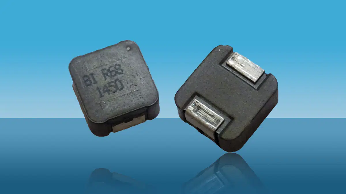
An optimum inductor can be chosen using TT Electronics (TT) inductor datasheets. In this example, TT part number HA72L-06308R2LFTR is suggested, which is automotive grade, -55 ºC to +155 ºC (AEC-Q200 certified) with the electrical parameters below:

TT p/nL @ 0 ampDCR typicalDCR maxI rmsI dc (sat) 30% Roll offTypical picture
HA72L-06308R2LFTR8.2 µH64 mΩ68 mΩ4.0 amps gives about 40 ºC Temp Rise7.5 amps
Table 1. Data sheet specification for TT part HA72L-06308R2LFTR
HA72L-06308R2LF DC bias and Temp rise
Figure 3. DC-DC Buck converter Inductor DC bias and Temp rise example

Figure 3 shows the inductance roll-off is 100 = 6.1% at 4.42 amps DC, which is close to the required value of 7.56 µH with a temperature rise of less than 40 °C.

The temperature rise in the data sheet graph is for DC current. In the example, there is also AC ripple current. A more precise temperature rise calculation, including ohmic and AC loss effects in the core and wire, is beyond the scope of this article but would be dependent on the below parameters:

  1. Skin depth at the operating frequency
  2. Surface area of the inductor
  3. Wire resistance at the operating temperature
  4. AC flux density, BAC, calculated from peak current, inductance, core cross sectional area and number of turns

TT Electronics has provided numerous solutions to the medical, automotive, and various industrial sectors. They provide semi and full custom designs to meet your critical specifications.

Read more in article: Buck Converter Design and Calculation

Related

Source: TT Electronics

Recent Posts

TDK and TAIYO YUDEN business alliance announcement for advanced MLCCs and inductors supporting AI infrastructure.

TDK and TAIYO YUDEN Explore Alliance for MLCCs and Inductors

29.9.2026
5
Coilcraft CSX7045 surface-mount current sense transformers with compact chip-style package

Coilcraft Extends Current Sense Transformers with 1.8 kVrms Isolation

29.9.2026
4
TLVR multiphase coupled inductors, auxiliary ballast inductor

TLVR Coupled Inductors: Fast Load-Step Response and Current-Dependent Ballast-Inductor Optimisation

24.9.2026
40

Bourns Adds ACXX57SQ Air Coil Inductors for RF Design

18.9.2026
17
Frenetic planar ER transformer simulation for a 5 kW 800 V-to-50 V PSFB converter, showing low-profile core geometry and high-current planar winding arrangement

5 kW 800 V-to-50 V PSFB Transformer Design for Data Centers

18.9.2026
54

On-Chip 3D-Printed Copper Microinductors: A New Route to Compact RF Electronics

10.9.2026
39
Murata DLW32SH_MF 1210 surface-mount common mode choke coil with metal terminals for automotive CAN FD signal-line noise suppression

Murata Introduces Common Mode Chokes for Automotive CAN FD up to 150°C

10.9.2026
51
onsemi solid-state transformer concept for 800 V HVDC AI data center power conversion with SiC modules, DC-link capacitors and high-frequency magnetics

Solid-State Transformers for 800 V AI Data Centers: Passive Component Design Considerations

9.9.2026
169

Coilcraft Introduces Automotive Common Mode Chokes Target CISPR 25 Class 5 EMC Compliance

7.9.2026
32

Upcoming Events

Sep 30
15:00 - 16:00 CEST

Positronic Space and Military Connectors

Oct 14
17:00 - 18:00 CEST

Live Demo! Discover KYOCERA AVX Antenna Integrator Studio (AIS)

Oct 19
15:00 - 16:00 CEST

ESCC-qualified Pt Temperature Sensors for Space Applications

View Calendar

Popular Posts

  • Buck Converter Design and Calculation

    0 shares
    Share 0 Tweet 0
  • Boost Converter Design and Calculation

    0 shares
    Share 0 Tweet 0
  • LLC Resonant Converter Design and Calculation

    0 shares
    Share 0 Tweet 0
  • Flyback Converter Design and Calculation
    0 shares
    Share 0 Tweet 0
  • Capacitor Charging and Discharging

    0 shares
    Share 0 Tweet 0
  • Resistor Symbols

    0 shares
    Share 0 Tweet 0
  • Thermistors Basics, NTC and PTC Thermistors

    0 shares
    Share 0 Tweet 0
  • Audio Capacitors: Choosing Capacitors for Crossover Circuits

    0 shares
    Share 0 Tweet 0
  • Capacitor Symbols

    0 shares
    Share 0 Tweet 0
  • MLCC and Ceramic Capacitors

    0 shares
    Share 0 Tweet 0

Newsletter Subscription


Passive Components Blog

© 2015–2026
All rights reserved

  • Home
  • Privacy Policy
  • EPCI Membership & Advertisement
  • About

No Result
View All Result
  • Home
  • Knowledge Blog
  • Dossiers
  • PCNS

© 2015–2026
All rights reserved