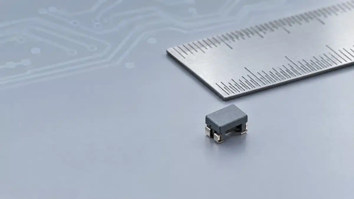
Murata has introduced the DLW32SH_MF series of surface-mount common mode choke coils for noise suppression on automotive CAN and CAN FD signal lines.
The Murata new series combines a 1210-inch footprint with a metal-terminal structure, AEC-Q200 compliance, and operation up to 150°C, addressing network interfaces located in high-temperature vehicle zones.
Key features and benefits
- Automotive CAN FD focus: Murata positions the DLW32SH_MF series for common-mode noise suppression on CAN and CAN FD networks, where higher communication speed can increase sensitivity to conducted and radiated noise.
- High-temperature capability: The published operating-temperature range is -55°C to +150°C, allowing evaluation in ECUs and network nodes exposed to elevated under-hood or locally self-heated conditions.
- Compact footprint: The components use a 1210-inch package size, specified as 3.2 mm × 2.5 mm.
- Metal-terminal structure: Murata states that the new terminal construction is intended to provide high reliability and durability. The announcement does not provide comparative test data against earlier products, so the relevant qualification documentation and current datasheet should be reviewed for final assessment.
- AEC-Q200 compliance: This is a passive-component stress-test qualification standard. It supports component-level qualification, but it does not replace vehicle-, module-, or system-level validation.
Technical highlights
| Part number | Common-mode inductance | Rated current at 125°C | Rated current at 140°C | Rated current at 150°C | Maximum DC resistance |
|---|---|---|---|---|---|
| DLW32SH510MF2 | 51 µH, +50%/-30% at 0.1 MHz | 125 mA | 90 mA | 50 mA | 1.5 Ω |
| DLW32SH101MF2 | 100 µH, +50%/-30% at 0.1 MHz | 115 mA | 90 mA | 50 mA | 2.1 Ω |
Both listed parts are specified for an operating-temperature range of -55°C to +150°C and are stated by Murata to comply with AEC-Q200.
The rated-current values are explicitly temperature dependent. For design engineers, this means the 150°C current rating—not the 125°C figure—must be used when the final local ambient temperature, copper temperature, and component self-heating can approach the maximum operating condition.
Common-mode inductance is specified at 0.1 MHz with a broad +50%/-30% tolerance. It is therefore not sufficient on its own to predict attenuation across the CAN FD spectrum. The current datasheet should be checked for impedance-versus-frequency characteristics, differential-mode behaviour, and applicable measurement conditions.
Typical applications
Murata identifies automotive CAN and CAN FD signal lines as the intended application area. Relevant circuit locations may include:
- Body-control modules and gateway ECUs
- ADAS control units and sensor-network interfaces
- Battery-management-system communication links
- Powertrain and chassis network nodes
- Automotive modules where a CAN/CAN FD interface is located close to noise-generating switching circuits
A common mode choke is placed in series with the two conductors of a differential data pair. It is intended to impede noise that appears in phase on both lines while preserving the wanted differential communication signal. Correct selection requires system-level confirmation that the device does not compromise the physical-layer signal margin.
For broader context, see this guide to common mode choke selection for DC and data signal lines.
Application fit
The DLW32SH_MF series is relevant where a CAN or CAN FD connection needs common-mode noise suppression and the thermal environment may exceed the capability of lower-temperature components. The stated 150°C capability can be important in modules installed near hot vehicle zones, but the actual part temperature must still be derived from the assembled board and enclosure conditions.
The compact 3.2 mm × 2.5 mm footprint can support dense ECU layouts. However, package area alone does not establish mechanical robustness: PCB bending, terminal-pad geometry, solder-joint quality, mounting orientation, and local board stiffness should be evaluated for the finished assembly.
Design-in notes for engineers
- Validate signal integrity: Check the final CAN/CAN FD transceiver, cable, common-mode choke, termination network, connectors, and PCB routing together. Verify eye performance, timing margin, common-mode voltage range, and communication robustness across supply, temperature, and network-load conditions.
- Review frequency data: Select the inductance value using the official impedance and attenuation characteristics at frequencies relevant to the noise problem. A 0.1 MHz inductance rating does not directly define high-frequency EMC performance.
- Apply temperature derating: Use the published current limit applicable to the expected component temperature. At 150°C, both announced part numbers are rated at 50 mA.
- Check DC resistance: The maximum DC resistance contributes to series voltage drop and resistive dissipation. Confirm its effect on the CAN transceiver’s differential output and common-mode operating conditions.
- Verify common- and differential-mode behaviour: A choke intended to suppress common-mode energy can also introduce parasitic effects that influence differential data transmission. Validate with the actual cable harness, termination arrangement, and transceiver.
- Control PCB layout: Keep the choke close to the connector or defined interface boundary where appropriate, maintain pair symmetry, minimise stubs, and avoid routing the filtered interface near aggressive switching-current loops.
- Confirm qualification scope: AEC-Q200 compliance is relevant for component screening, but final release still requires the applicable automotive customer requirements, ECU validation plan, EMC tests, thermal tests, and reliability assessments.
- Use current documentation: Murata’s current datasheet, product documentation, land-pattern recommendation, packaging details, and reliability information control final schematic, layout, purchasing, and production release.
For practical background on EMC filters and the role of common mode chokes, see EMC Design Fundamentals: Safe Use of Varistors and Common Mode Chokes in Mains and Data-Line Filters.
Further reading
- Common Mode Chokes Selection for RF Circuits in Next-Generation Communication Systems
- EMC Design Fundamentals: Safe Use of Varistors and Common Mode Chokes in Mains and Data-Line Filters
- Murata Releases 1210 Metal Terminal Common Mode Choke for 10Base‑T1S In‑Vehicle Ethernet
- Murata Expands High Cutoff Frequency Chip Common Mode Chokes
Source
This article is based on Murata’s manufacturer press release announcing the DLW32SH_MF series. Engineers should consult the current Murata datasheet and applicable product documentation before final component qualification, schematic release, PCB release, or production approval.