



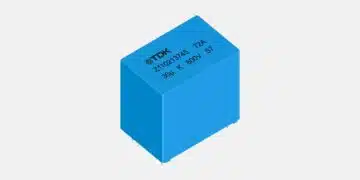


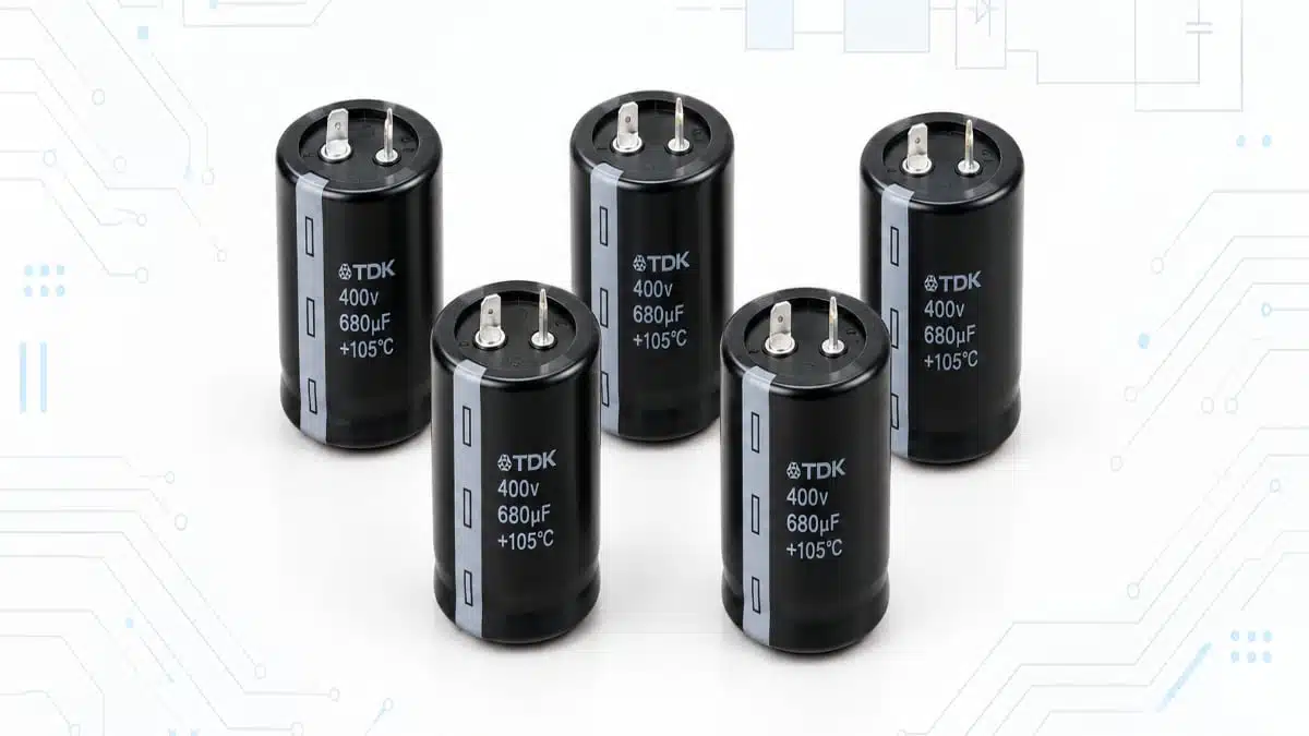
TDK has expanded six ultra-compact snap-in aluminum electrolytic capacitor series—B43645, B43657, B43658, B43659, B43660, and B43661—with rated DC voltages reaching 500 V.
The announcement targets AI-server power supplies and other high-performance switch-mode power supplies where DC-bus energy storage, ripple-current capability, board area, and thermal conditions must be balanced carefully.
Key features and benefits
- New voltage extension: The B43657 and B43658 series now cover ratings up to 500 V DC; the B43645 range extends to 475 V DC, while B43659, B43660, and B43661 cover ratings up to 450 V or 475 V, depending on series.
- Compact snap-in format: TDK states that the series use case diameters from 22 mm to 35 mm and lengths from 25 mm to 100 mm, supporting dense PSU layouts where capacitor volume is constrained.
- Capacitance range: Across the announced series, the published range is 80 µF to 2060 µF.
- Ripple-current capability: The highest stated rating is 5.39 A at 120 Hz and +105 °C. Ripple-current capability is a primary thermal selection parameter because capacitor losses rise with ESR and RMS ripple current.
- Lifetime ratings: The press release lists useful-life values exceeding 2,000 h, 3,000 h, or 5,000 h at +105 °C, rated voltage, and rated AC ripple current, according to the individual series.
- Mechanical options: Standard versions have two terminals; three-terminal versions are available to support correct insertion. The capacitors include an aluminum can, PET sleeve, snap-in terminals, and an integrated pressure-relief feature.
- Compliance and vibration: TDK states that all types are RoHS-compatible and vibration-tested according to IEC 60068-2-6.
Technical highlights
| Series | Rated DC voltage | Rated capacitance | Useful life at +105 °C, rated voltage and ripple current | Maximum stated ripple current at 120 Hz, +105 °C |
|---|---|---|---|---|
| B43645 | 400–475 V | 110–1960 µF | >5,000 h | 5.34 A |
| B43657 | 420–500 V | 80–2060 µF | >2,000 h | 5.36 A |
| B43658 | 420–500 V | 80–2060 µF | >3,000 h | 5.39 A |
| B43659 | 420–450 V | 140–1440 µF | >2,000 h | 3.37 A |
| B43660 | 450–475 V | 460–1320 µF | >2,000 h | 3.54 A |
| B43661 | 450–475 V | 440–1300 µF | >3,000 h | 3.58 A |
The published data show that the announcement is not a single uniform capacitor range. Engineers must select the relevant series first, then verify the exact part-number datasheet for capacitance, case size, ripple-current rating, ESR or impedance, endurance conditions, terminal configuration, and permitted operating conditions.
The 500 V rating can be relevant for high-voltage bulk-storage or DC-link positions in offline power-conversion systems. It does not by itself establish suitability for a particular bus voltage: the complete voltage profile, including steady-state level, start-up, abnormal mains conditions, surge events, balancing in series-connected capacitors, and fault conditions, must be assessed.
Typical applications
TDK identifies the following application areas:
- AI-server power supply units
- Switch-mode power supplies
- Uninterruptible power supplies
- Solar inverters
In a high-power AC/DC front end, snap-in aluminum electrolytic capacitors are commonly used after rectification and PFC to store energy and limit low-frequency bus-voltage ripple. In UPS and inverter systems, they may also provide bulk energy storage on intermediate DC buses. Their suitability depends on the actual ripple spectrum, thermal environment, switching topology, hold-up requirement, and service-life target.
Application fit
| Design question | Practical implication |
|---|---|
| Is 500 V DC sufficient? | Compare the rating with normal DC-bus voltage, line tolerance, transient conditions, start-up behaviour, and credible fault cases. Do not treat rated voltage as a substitute for a system-level transient assessment. |
| Is capacitance adequate? | Evaluate bulk-energy, hold-up-time, bus-ripple, and control-loop requirements at minimum capacitance over the intended operating life. |
| Is ripple-current capability sufficient? | Use the capacitor RMS ripple current and frequency spectrum at the actual hot-spot temperature. The published maximum values are specified at 120 Hz and +105 °C. |
| Will lifetime meet the system target? | The stated useful life is tied to defined rated conditions. Estimate life at the real capacitor hot-spot temperature and electrical stress, then validate the result with the current manufacturer documentation. |
| Will the mechanical package fit? | Check exact diameter, height, lead spacing, pin layout, polarity marking, clearance to heatsinks and enclosures, airflow, and access to the pressure-relief vent. |
Design-in notes for engineers
- Check the complete voltage envelope. Verify normal operating voltage, mains-derived overvoltage, load-dump or switching transients where applicable, start-up overshoot, and discharge behaviour. The current manufacturer datasheet controls final voltage qualification.
- Model capacitor heating. Ripple-current capability should be checked together with ESR, ripple frequency, ambient temperature, airflow, copper area, capacitor spacing, and the effect of adjacent magnetic and semiconductor heat sources.
- Use the correct life condition. The announced endurance figures are quoted at +105 °C, rated voltage, and rated ripple current. They should not be translated directly into calendar life without an application-specific thermal and electrical assessment.
- Verify frequency-dependent parameters. The press release gives the headline ripple-current condition at 120 Hz. Confirm impedance, ESR, permitted ripple current, and correction factors at the actual frequency content of the converter.
- Confirm actual mechanical data. The overall published envelope is 22–35 mm diameter and 25–100 mm length, but exact dimensions and terminal options are part-number dependent.
- Review venting and placement. Maintain the manufacturer’s required clearance around the pressure-relief feature and avoid arrangements that direct heat from power semiconductors or magnetics into the capacitor bank.
- Validate the final assembly. Confirm soldering or mounting process limits, vibration requirements, polarity control, capacitor-bank current sharing, inrush stress, discharge-path design, and thermal performance on production-representative hardware.
- Use application-specific life calculation. TDK provides its web-based AlCap Tool for lifetime calculation under stated application conditions; tool output should still be checked against the current series documentation and final measurement results.
Further reading
- Aluminum Electrolytic Capacitors for DC-Link On-Board Charger Applications
- TDK Compact Aluminum Capacitors with High Ripple Current
- KEMET Design it Day: DC Link Capacitor Selection Guide
- TDK DC Link Aluminum Capacitors for EV On-Board Chargers
Source
This article is based on the TDK manufacturer press release announcing the voltage extension of its B43645, B43657, B43658, B43659, B43660, and B43661 ultra-compact snap-in aluminum electrolytic capacitor series. Engineers should consult the current manufacturer datasheet, product-family documentation, and application-specific calculation tools before final component qualification and design release.