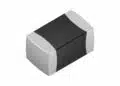






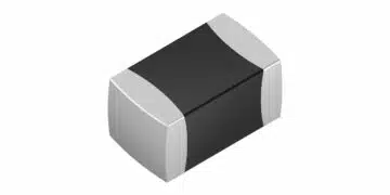



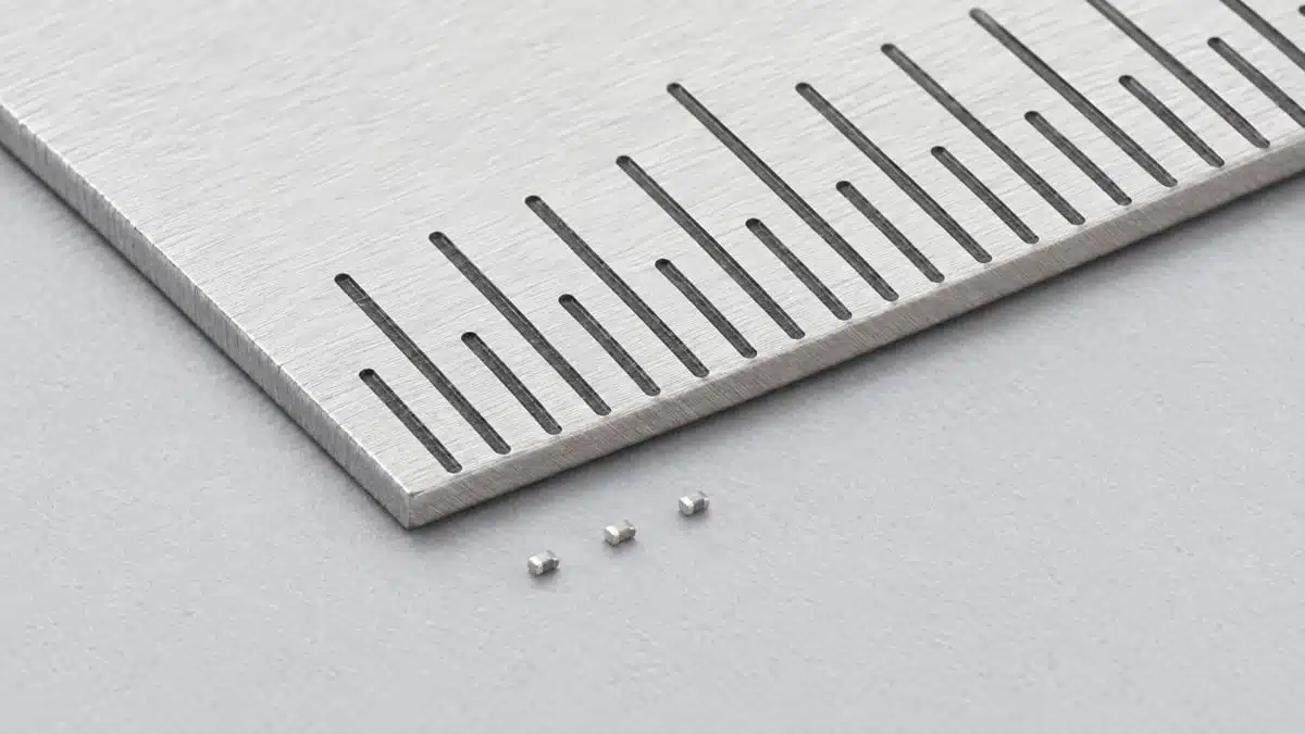
Murata has introduced the NCU01 series of NTC thermistors in an 008004-inch size measuring 0.25 mm × 0.125 mm.
The Murata NTC thermistors series combines this footprint with ±1% resistance tolerance and ±1% B-constant tolerance, enabling temperature sensors to sit closer to heat-generating components in densely populated boards and modules.
Key features and benefits
- Dimensions of 0.25 mm × 0.125 mm support temperature sensing where component placement space is restricted.
- Mounting area is approximately 60% smaller than Murata’s previous smallest 01005-inch product, measuring 0.4 mm × 0.2 mm.
- Resistance tolerance and B-constant tolerance are both ±1%, matching the corresponding tolerances of the previous size.
- Initial resistance options are 100 kΩ and 10 kΩ, with further lineup expansion planned.
- Target applications include smartphone and wearable circuit boards, integrated circuit packages, and system-in-package modules.
The principal change is the space needed to position the sensor. A smaller thermistor can fit nearer the component being monitored, helping reduce the temperature difference and detection delay associated with a more distant measurement point.
Technical highlights
| Parameter | NCU01 series |
|---|---|
| Component type | NTC thermistor |
| Inch size designation | 008004 |
| Dimensions | 0.25 mm × 0.125 mm |
| Initial resistance options | 100 kΩ and 10 kΩ |
| Resistance tolerance | ±1% |
| B-constant tolerance | ±1% |
| Mounting-area reduction | Approximately 60% |
| Comparison product size | 01005 inch |
| Comparison product dimensions | 0.4 mm × 0.2 mm |
Resistance and B-constant tolerance
An NTC thermistor’s resistance falls as temperature rises. Its resistance–temperature characteristic provides the basis for converting a measured resistance into temperature.
Resistance tolerance governs the spread in resistance at a reference temperature. B-constant tolerance governs variation in the temperature dependence of resistance. Both matter when setting temperature thresholds or calculating the sensing error across the intended operating range.
The ±1% values are component tolerances, not a temperature-accuracy rating. Circuit-level accuracy also depends on the resistance–temperature characteristic, the fixed resistor used in the sensing circuit, and measurement conditions.
Sensor placement and self-heating
Placement is central to the NCU01’s application value. A thermistor located away from the heat source can measure a different temperature and detect changes later than a sensor positioned nearby.
Excitation introduces a separate source of error. Current flowing through the thermistor generates heat, raising its temperature and reducing its resistance. The measurement circuit should therefore keep self-heating small enough for the required sensing accuracy. Heat dissipation also depends on the mounting environment, including the substrate, land geometry and surrounding materials.
Typical applications
Smartphone and wearable circuit boards
The 0.25 mm × 0.125 mm dimensions support placement in restricted board areas near heat-generating components. The approximately 60% mounting-area reduction relative to the previous 01005-inch product provides additional placement flexibility while retaining ±1% resistance and B-constant tolerances.
IC packages and system-in-package modules
The NCU01 series also targets temperature monitoring inside integrated circuit packages and system-in-package modules. Its dimensions address the limited space available for sensing components within these assemblies.
In both board-level and package-level implementations, the relevant temperature is the temperature at the sensor location. Positioning the thermistor close to the monitored component helps reduce the difference between that measurement and the heat-source temperature.
Design-in notes for engineers
- Select the resistance option together with the sensing circuit’s fixed resistor and excitation conditions. A thermistor and fixed resistor connected in series form a voltage divider whose output changes with temperature.
- Use the resistance–temperature characteristic when converting the measured signal into temperature. Include thermistor and fixed-resistor tolerances in the error budget.
- Keep excitation-induced self-heating within the sensing error budget.
- A shared supply for the sensing divider and ADC reference can cancel the effect of supply variation on the conversion.
- Assess sensor position alongside electrical tolerance. Distance from the heat source affects both the measured temperature and the delay in detecting a temperature change.
- Validate the final sensing circuit and thermal response under actual operating conditions before production release.
Availability
Sample shipments are planned to begin in October 2026, with mass production planned during 2027. The initial lineup will begin with 100 kΩ and 10 kΩ resistance options and expand progressively.
Further reading
- Thermistor-Based Temperature Sensing System Explained
- Thermistor Temperature System Optimization and Evaluation
- How to Measure NTC Thermistor Resistance; Murata Video
Source
This article is based on the Murata product announcement and official product documentation. Engineers should refer to the current manufacturer datasheet for final design and qualification.
References
- Murata Develops World’s Smallest 008004-inch Size (0.25mm × 0.125mm) NTC Thermistor for Space-Constrained Temperature Sensing, Murata Manufacturing Co., Ltd., October 20, 2026.
- Basic Characteristics | Basic Knowledge of NTC Thermistor, Murata Manufacturing Co., Ltd.
- Application Note: NCP/NCU/NXFT/NXRT Series, Murata Manufacturing Co., Ltd., Rev. 1.2, July 2020.