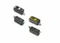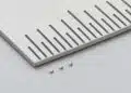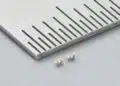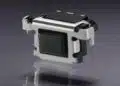

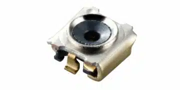





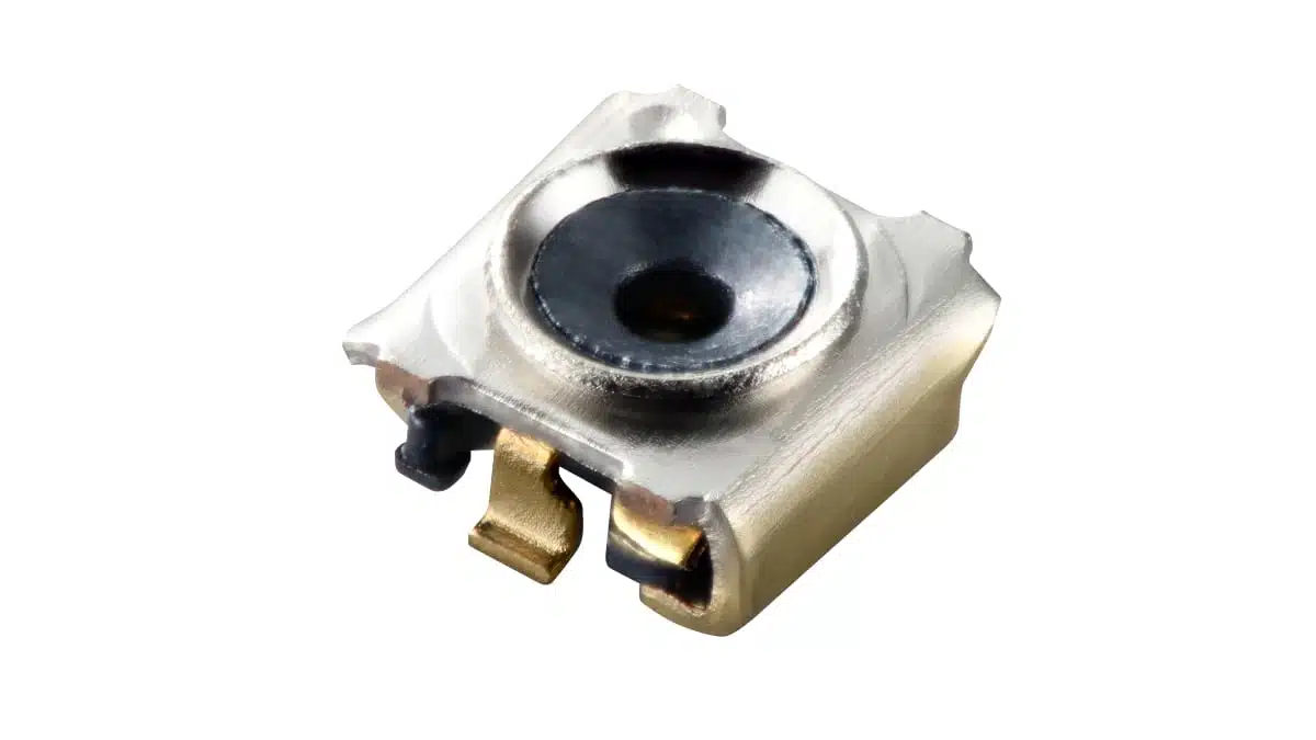
Murata has introduced the SWL series of RF/microwave coaxial connectors with an integrated mechanical switch for circuit measurement in wireless devices.
The MM8330-2600 family measures 1.0 × 1.0 × 0.55 mm and supports DC to 15 GHz at a nominal impedance of 50 Ω. Its smaller connector body and dedicated probes reduce the board space needed for both the test point and measurement access.
Key features and benefits
- Connector dimensions of 1.0 × 1.0 × 0.55 mm, compared with 1.4 × 1.2 × 0.65 mm for the SWJ series.
- Approximately 40% less connector mounting area than SWJ.
- Approximately 60% less occupied PCB area, including probe-access clearance, when used with dedicated probes.
- DC-to-15 GHz frequency coverage for RF circuit measurement.
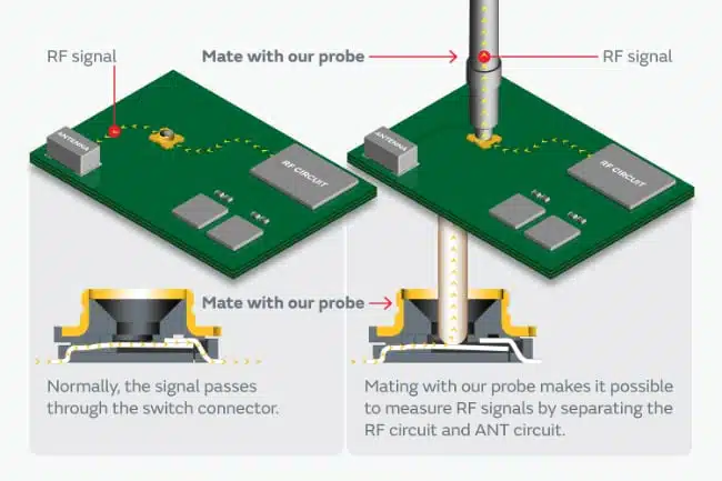
- An integrated mechanical switch that separates the RF circuit from the antenna circuit during probing.
- Two reel options: MM8330-2600RJ5 with 5,000 pieces and MM8330-2600RK20 with 20,000 pieces.
Technical highlights
Electrical and mechanical selection
The SWL series combines a switched measurement interface with a 50 Ω signal path. Unlike a permanent cable connection, the test connector remains in the RF transmission line and provides access when a dedicated probe is engaged.
| Parameter | SWL series |
|---|---|
| Base part number | MM8330-2600 |
| Frequency range | DC to 15 GHz |
| Nominal impedance | 50 Ω |
| Length × width × height | 1.0 × 1.0 × 0.55 mm |
| Mounting-area reduction versus SWJ | Approximately 40% |
| Occupied-area reduction with dedicated probes | Approximately 60% |
The distinction between mounting area and keep-out area matters during layout. The connector body occupies board space permanently; the probe also needs clearance around the measurement point. Reducing both allows nearby components to be placed closer to the RF test interface.
The smaller dimensions also involve a frequency-range trade-off within the product family. SWL supports frequencies up to 15 GHz, while SWJ supports frequencies up to 20 GHz. Selection therefore depends on the required measurement band as well as the available board area.
How the switched test point works
Without a probe engaged, the internal mechanical switch connects the RF circuit to the antenna circuit. Engaging the dedicated probe separates these circuits and provides measurement access without their mutual interaction.
This arrangement supports inspection of internal RF circuitry through a board-mounted test point. The choice of RF connector and measurement interface should account for the operating frequency, nominal impedance and physical access needed by the test setup.
Typical applications
Target applications include:
- Mobile phones and smartphones.
- Wearable devices and smartwatches.
- True wireless stereo earphones.
- AR and VR glasses.
The 1.0 × 1.0 mm body and 0.55 mm height address placement constraints in these devices. DC-to-15 GHz coverage supports internal RF output inspection, while the dedicated probe interface provides access for circuit evaluation and production measurement.
Design-in notes for engineers
- Place the connector in the RF transmission line at the intended circuit-measurement position.
- Plan connector placement and probe clearance together. The approximately 60% occupied-area reduction depends on the dedicated probe arrangement, not the connector body alone.
- Match the measurement path to the 50 Ω nominal impedance and keep the required measurement band within DC to 15 GHz.
- Select the dedicated manual or automatic probe to suit the measurement workflow.
- Account for cable loading during manual probing. Stress transmitted through an engaged probe can detach the probe, damage the connector or peel the electrode.
- Validate the assembled RF path and probe engagement under actual operating and test conditions before production release.
Production and purchasing
The SWL connectors are in mass production. The two ordering options provide different reel quantities:
| Ordering part number | Pieces per reel |
|---|---|
| MM8330-2600RJ5 | 5,000 |
| MM8330-2600RK20 | 20,000 |
Dedicated automatic and manual probes are scheduled to enter mass production in December 2026. Connector procurement and test-fixture planning should therefore be coordinated with the probe production schedule.
Further reading
Source
This article is based on the Murata product announcement and official product documentation. Engineers should refer to the current manufacturer datasheet for final design and qualification.
References
- Murata Launches World’s Smallest RF / Microwave Coaxial Connectors with a Switch, Cutting PCB Mounting Area by Approximately 40%, Murata Manufacturing Co., Ltd., October 29, 2026.
- SWL Series | RF / Microwave Coaxial Connectors with Switch, Murata Manufacturing Co., Ltd.
- RF / Microwave Coaxial Connectors with Switch, Murata Manufacturing Co., Ltd.