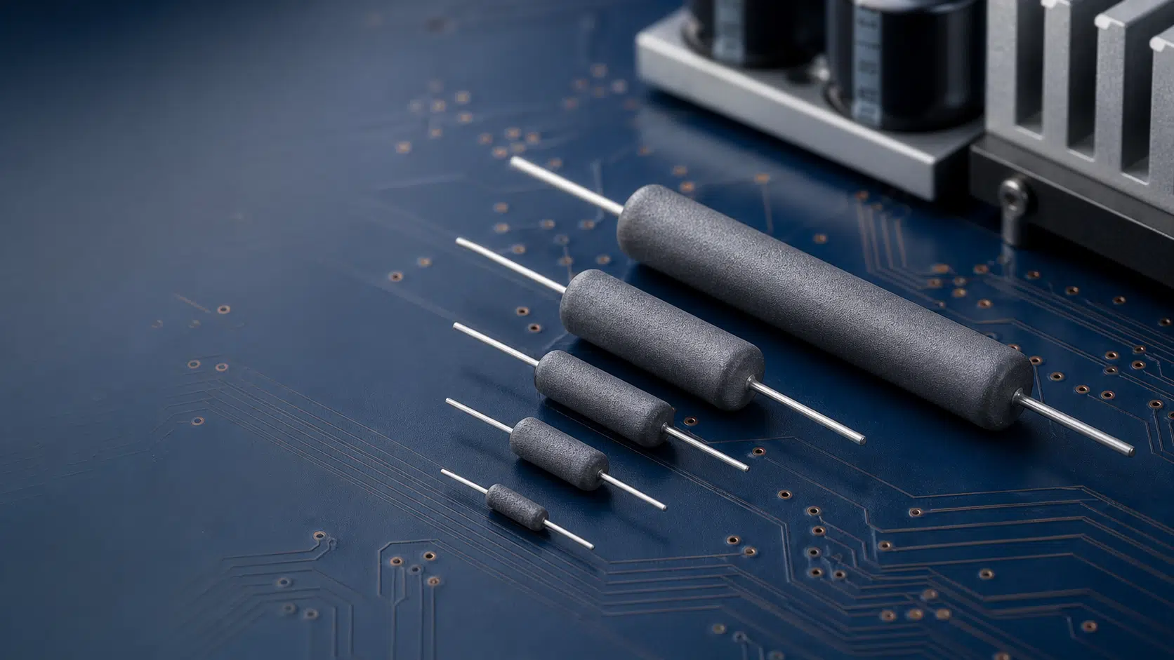
Bourns has introduced the UT-A Series of through-hole wirewound power resistors for applications requiring stable resistance, pulse capability, and operation at elevated temperatures.
The AEC-Q200-compliant resistor series spans 1 W to 10 W ratings and is intended for energy-storage, industrial-power, inverter, motor-drive, and telecommunications equipment.
Key features and benefits
- Wirewound construction supports applications where pulse loading, continuous dissipation, and resistance stability are more critical than extreme miniaturisation.
- AEC-Q200 compliance makes the series relevant to automotive-grade design programmes, although final suitability must still be verified at the individual part-number and system level.
- Low temperature coefficient of resistance: the standard TCR is ±30 ppm/°C, helping limit resistance change as the component temperature varies.
- Wide operating-temperature range: specified from -55 °C to +150 °C.
- Silicone coating provides an insulated exterior for a conventional leaded power-resistor format.
- Through-hole construction can be useful where leaded assembly, mechanical robustness, or board-level spacing for thermal management is preferred.
- Customisation is available on request, according to Bourns.
Technical highlights
| Parameter | Bourns UT-A Series |
|---|---|
| Resistor technology | Wirewound |
| Package style | Through-hole, silicone-coated |
| Rated power range | 1 W to 10 W |
| Resistance range | 10 Ω to 4.5 kΩ |
| Resistance tolerance | Down to ±1% |
| Standard TCR | ±30 ppm/°C |
| Operating temperature | -55 °C to +150 °C |
| Qualification claim | AEC-Q200 compliant |
| Environmental status | RoHS compliant |
A TCR of ±30 ppm/°C corresponds to a nominal resistance shift of up to 0.003% per degree Celsius relative to the reference temperature. In practical power circuits, this supports more predictable current limiting, discharge timing, or voltage-setting performance as enclosure and component temperatures change.
The stated 1 W to 10 W power range does not by itself establish the permissible dissipation in a specific design. Engineers should apply the applicable temperature derating curve and evaluate board layout, airflow, nearby heat sources, and pulse repetition rate before releasing the design.
Typical applications
Bourns identifies the UT-A Series for:
- Energy-storage equipment
- Industrial power supplies
- Inverters and motor drives
- Capacitor recharge and discharge circuits
- Voltage regulators
- Telecommunications equipment
The combination of wirewound technology and pulse-handling capability is particularly relevant to resistive functions that must absorb transient energy rather than merely set a low-power bias or feedback value. Examples include charging-path current limitation, controlled discharge of stored energy, and damping or protection functions in industrial conversion equipment.
Application fit
| Circuit function | Why the UT-A Series may fit | Key verification point |
|---|---|---|
| DC-link capacitor discharge | Resistance range and power capability can support controlled discharge paths for stored energy | Calculate resistor pulse energy, average dissipation, discharge time, and maximum resistor temperature |
| Capacitor recharge current limiting | Wirewound construction and stated pulse performance suit repetitive charging events | Confirm peak current, pulse duration, repetition rate, and worst-case supply tolerance |
| Inverter and motor-drive auxiliaries | High-temperature operation can suit electrically noisy, thermally demanding power assemblies | Check vibration, creepage/clearance, mounting, and local ambient temperature |
| Industrial power-supply loads | Low TCR and tight tolerance support stable resistive control or loading functions | Confirm voltage stress and derating at the actual operating temperature |
| Telecom power equipment | Through-hole mounting can provide robust mechanical retention in power sections | Verify component height, lead spacing, assembly process, and thermal clearance |
Design-in notes for engineers
- Use the manufacturer’s pulse-load information for the selected UT-A part number; a general “excellent pulse handling” statement is not a substitute for a time-, energy-, and repetition-rate-specific assessment.
- Separate single-event energy verification from repetitive-pulse average-power verification. Repetitive pulses can cause excessive body temperature even when each individual pulse is within a short-duration limit.
- Apply continuous-power derating for the real resistor ambient temperature, not only the system’s nominal ambient rating. Nearby magnetics, semiconductors, and DC-link capacitors may create a much hotter local environment.
- Consider leaded-resistor spacing above the PCB as part of the thermal design. Adequate clearance can reduce heat transfer into the board and temperature-sensitive neighbouring components.
- Check working-voltage capability and any applicable voltage-versus-resistance limitation in the current datasheet. Neither maximum working voltage nor dimensions are specified in the release.
- For automotive programmes, treat AEC-Q200 compliance as an important component qualification input, while retaining normal system-level validation for mechanical loading, temperature cycling, humidity, electrical transients, and the complete assembly.
- Review resistor pulse-load, power and voltage derating before setting margins for a charging, discharge, or surge-energy duty.
- For technology background, see wirewound resistor construction, pulse load and types.
Further reading
- Resistors Pulse Load and Derating Design Guide
- Wirewound Resistors: Construction, Pulse Load and Types
- Performance of AEC-Q200 Rated Power Resistors for Automotive Use
- Top Ten Harsh Environment Resistors
Source
This article is based on the Bourns UT-A Series manufacturer press release. Engineers should consult the current manufacturer datasheet and associated documentation for final component selection, qualification, derating, pulse-load assessment, and design release.