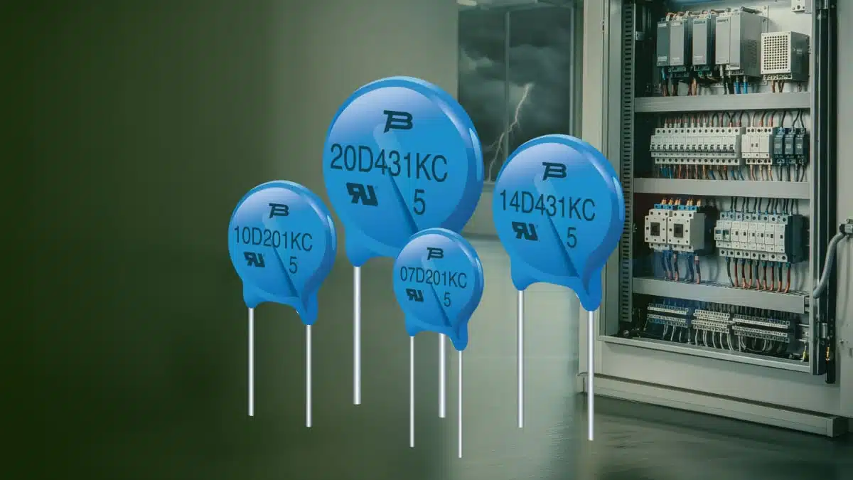
Bourns has introduced four radial-leaded metal oxide varistor (MOV) series for transient protection in line-voltage equipment: MOV-07DxxxKC, MOV-10DxxxKC, MOV-14DxxxKC, and MOV-20DxxxKC.
The new copper-electrode MOV family scales from 7 mm to 20 mm disc diameters, allowing designers to match surge-current capability and continuous-voltage requirements to the protected AC or DC line.
The series is intended for high-energy overvoltage protection where conventional leaded disc MOVs are needed at the power entry or across line-connected circuitry. Bourns states that the copper-electrode construction provides surge and energy performance comparable to conventional silver-electrode MOV designs while supporting cost-optimised implementation.
Key features and benefits
- Four scalable disc sizes: 7 mm, 10 mm, 14 mm, and 20 mm devices enable a practical step-up in surge-current handling without changing to a different component technology.
- High 8/20 microsecond surge ratings: Peak surge-current capability reaches 1,200 A, 2,500 A, 4,500 A, and 6,500 A respectively across the four series, depending on the voltage rating.
- Broad voltage selection: The smaller 7 mm and 10 mm versions cover 200 V to 820 V varistor voltages, while 14 mm and 20 mm versions extend to 1,800 V.
- Copper-electrode construction: According to Bourns, this construction targets surge and energy capability comparable to silver-electrode MOVs, with potential bill-of-material advantages in volume applications.
- Flexible PCB mounting: Straight, outward-kinked, and in-line kinked lead versions support alternative lead spacing, board layout, and assembly arrangements.
- UL 1449 recognised and RoHS compliant: The recognition is relevant to surge-protection equipment design, although final product-level compliance depends on the complete protection circuit and end-equipment evaluation.
Technical highlights
| Parameter | MOV-07DxxxKC | MOV-10DxxxKC | MOV-14DxxxKC | MOV-20DxxxKC |
|---|---|---|---|---|
| Disc diameter | 7 mm | 10 mm | 14 mm | 20 mm |
| Varistor-voltage range | 200 V to 820 V | 200 V to 820 V | 200 V to 1,800 V | 200 V to 1,800 V |
| Maximum continuous voltage, RMS | 130 V to 510 V | 130 V to 510 V | 130 V to 1,100 V | 130 V to 1,100 V |
| Peak surge current, 8/20 microsecond | Up to 1,200 A | Up to 2,500 A | Up to 4,500 A | Up to 6,500 A |
| Varistor-voltage tolerance | ±10% | ±10% | ±10% | ±10% |
| Operating temperature | −40 °C to +105 °C | −40 °C to +105 °C | −40 °C to +105 °C | −40 °C to +105 °C |
Bourns specifies a typical response time of 10 ns to 25 ns. In practice, an MOV begins clamping quickly, but the actual voltage appearing at the protected circuit during a surge is also affected by MOV clamping voltage, lead inductance, PCB current-loop geometry, and the surge source impedance.
The stated RMS continuous-voltage range is particularly important for mains-connected equipment. An MOV must tolerate the highest continuous line voltage, including permitted line variation and foreseeable overvoltage conditions, without excessive leakage or accelerated ageing.
Typical applications
Bourns identifies the series for:
- AC power supplies
- Power-distribution systems
- Line-voltage protection circuits
- Telecommunications equipment
- White goods and household appliances
- Level-control, tuning, and timer circuitry in line-connected equipment
The larger 14 mm and 20 mm disc options are likely to be most relevant where the expected surge environment requires higher 8/20 microsecond current capability or where a higher continuous-voltage class is required. Smaller 7 mm and 10 mm discs can fit lower-energy protection duties, auxiliary mains supplies, and compact control electronics, subject to the required surge test level and the manufacturer datasheet limits.
Application fit
| Design situation | Relevant consideration |
|---|---|
| Single-phase AC input | Select continuous RMS voltage with appropriate margin for nominal mains, tolerance, and abnormal steady-state conditions. |
| Power-entry surge stage | Use the MOV as a shunt element across the line path; coordinate it with upstream fusing, impedance, disconnect provisions, and the required surge test profile. |
| High-energy industrial input | Evaluate the 14 mm or 20 mm alternatives where the required peak surge current exceeds the capability of smaller discs. |
| Telecom or distributed-power equipment | Check both the normal operating voltage and the likely exposure to lightning-induced or switching transients. |
| Compact appliance controller | Kinked lead options can help accommodate existing PCB footprint and assembly constraints. |
For background on operating principles and selection fundamentals, see the Metal Oxide Varistors Overview and Supply Chain and How to Use Varistors as ESD/Surge Protection Devices.
Design-in notes for engineers
- Do not select solely by disc diameter. The device must satisfy the required continuous-voltage rating, surge-current waveform, clamping performance, pulse-energy capability, and expected end-of-life behaviour.
- Coordinate the protection network. A line MOV normally requires properly specified upstream overcurrent protection and must be evaluated together with fuses, thermal protection, PCB creepage and clearance, enclosure constraints, and the applicable end-equipment standard.
- Account for MOV ageing. Repeated surge exposure and sustained high-voltage stress can change MOV characteristics over its service life. Avoid operating too close to the maximum continuous voltage and assess lifetime under the actual line environment.
- Minimise inductive connection length. Keep the MOV leads and associated high-current loop short and wide where possible. Excess parasitic inductance can raise the transient voltage seen by downstream circuitry.
- Verify the surge waveform. The quoted peak-current ratings use an 8/20 microsecond waveform. This should not be treated as interchangeable with other test conditions, such as longer-duration mains overvoltage, combination-wave testing, or short-circuit fault events.
- Confirm mechanical ordering details. Straight and kinked lead arrangements can affect occupied board area, insertion process, lead pitch, and clearance around high-voltage nodes; confirm dimensions and ordering codes according to the current manufacturer datasheet.
For broader line-protection architecture, including coordination of MOVs with other protective devices, see Over-Voltage and Over-Current Protection Explained.
Further reading
- Metal Oxide Varistors Overview and Supply Chain
- How to Use Varistors as ESD/Surge Protection Devices
- Safe Use of Varistors and Common Mode Chokes for EMC
- Gas Discharge Tubes: Design, Selection and Surge Protection Fundamentals
Source
This article is based on the Bourns manufacturer press release covering the MOV-07DxxxKC, MOV-10DxxxKC, MOV-14DxxxKC, and MOV-20DxxxKC copper-electrode MOV series. Engineers should consult the current manufacturer datasheet and supporting documentation for final component qualification, ordering-code selection, safety assessment, and design release.