











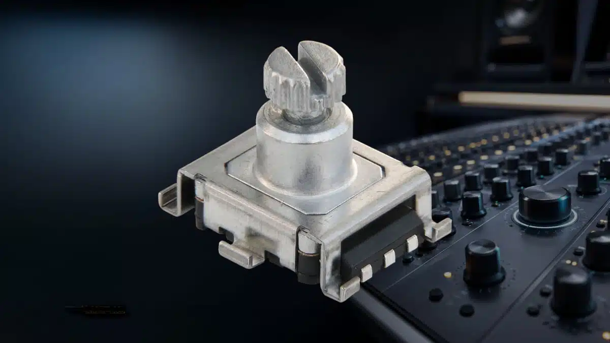
Bourns has expanded its PEC11S Series of 12 mm surface-mount incremental encoders with additional shaft-length choices and switch configurations.
The update gives HMI designers more mechanical flexibility while retaining a compact rotary-input device with quadrature output and an optional integrated push switch.
Key features and benefits
- 12 mm SMD incremental encoder: The PEC11S is intended for compact PCB-mounted control interfaces assembled using reflow soldering.
- Additional shaft-length options: The expanded range helps designers match front-panel depth, knob position, enclosure geometry, and mechanical stack-up without changing to a different encoder platform.
- Integrated momentary push switch: Selected versions combine rotary input with a normally open SPST push function, reducing the need for a separate panel switch in menu-selection or confirmation functions.
- 2-bit quadrature output: Two phased digital signals allow a controller to determine rotational movement and direction; the specified series resolution is 15 pulses per 360-degree rotation.
- Metal shaft and bushing: These features are intended to provide a mechanically robust interface between the encoder, knob, and panel or enclosure.
- Surface-mount terminals: The SMD gull-wing configuration supports automated assembly, but the manufacturer specifies a single reflow process and does not recommend hand soldering.
- IP40 construction: The IP40 rating indicates protection against solid objects larger than 1 mm; it does not indicate protection against water ingress.
Technical highlights
| Parameter | PEC11S Series specification |
|---|---|
| Encoder type | Contacting incremental encoder |
| Package diameter | 12 mm |
| Output | 2-bit quadrature code |
| Resolution | 15 pulses per 360-degree rotation |
| Detent option | 30 detents |
| Operating speed | 60 rpm maximum |
| Contact rating | 10 mA at 5 VDC |
| Closed-circuit resistance | 3 ohms maximum |
| Insulation resistance | 100 Mohms minimum at 250 VDC |
| Dielectric-withstanding voltage | 300 VAC minimum at sea level |
| Operating temperature | -40 degrees C to +70 degrees C |
| Storage temperature | -40 degrees C to +85 degrees C |
| Rotational life | 15,000 cycles minimum |
| Push-switch life | 20,000 cycles minimum |
| Ingress protection | IP40 |
| Moisture sensitivity level | MSL 1 |
The standard switch option has 0.5 mm nominal travel, while the high-travel option has 1.5 mm nominal travel. Both are momentary SPST functions, with specified resistive-load ratings of 10 mA at 5 VDC.
Available shaft configurations include metal flatted and knurled styles. According to the manufacturer ordering information, shaft lengths include 9.5 mm, 13.5 mm, 15.0 mm, 20.0 mm and, for the flat-shaft high-switch configuration, 25.0 mm.
Typical applications
Bourns identifies the PEC11S Series for level control, tuning and timer-setting functions in:
- Audio-visual equipment, including volume, balance, parameter adjustment, and menu navigation
- Consumer electrical appliances with compact control panels
- Radio tuning and user-interface adjustment
- Musical instruments and effects equipment requiring real-time parameter selection
- Communications equipment with local selection, setup, or adjustment controls
For equipment with a local display, the rotary-plus-push arrangement can support a familiar operating model: rotate to navigate or adjust a setting, then press to select or confirm it.
Application fit
| Design requirement | PEC11S relevance |
|---|---|
| Compact PCB assembly | The 12 mm SMD format is suited to reflow-compatible board assembly. |
| Rotary HMI control | Quadrature signals provide relative position and direction information to a microcontroller. |
| Combined rotation and selection | Switch-equipped versions integrate a momentary SPST push function. |
| Mechanical panel flexibility | Multiple shaft lengths help accommodate different panel thicknesses, knob depths, and display-front assemblies. |
| Moderate operating environment | The IP40 rating and -40 degrees C to +70 degrees C operating range should be checked against actual enclosure and environmental requirements. |
Unlike an analogue potentiometer, an incremental encoder does not provide an absolute voltage corresponding to knob position. Its controller must interpret pulses and establish any required reference position during system start-up or through software logic; see the overview of potentiometers, encoders, rheostats and trimmers.
Design-in notes for engineers
- Select shaft geometry early: Confirm the shaft length, flatted or knurled style, knob interface, panel thickness, and clearance to the PCB before locking the mechanical design.
- Allow for switch travel: The push-switch version requires appropriate axial clearance behind the knob and should be assessed for the desired tactile feel and operating force.
- Debounce the contacts: As a contacting encoder, the device can generate contact bounce. The datasheet gives 2.0 ms maximum contact bounce at 15 rpm, so firmware or external filtering should prevent false counts.
- Use suitable signal conditioning: The manufacturer’s suggested circuit uses pull-up resistors and 0.01 microfarad capacitors on the A and B outputs. Filter values should be verified against the intended rotation speed, controller input thresholds, and desired response time.
- Respect the low-level contact rating: The 10 mA at 5 VDC rating is appropriate for low-power logic inputs, not for switching a power load, relay coil, or LED supply directly.
- Follow the reflow guidance: Bourns recommends no-clean solder paste and advises against aqueous washing, water-soluble flux, and multiple soldering passes because of corrosion and process-risk considerations.
- Validate real-life endurance: The stated rotational and switch-cycle ratings are minimum specifications, but knob mass, side loading, press force, contamination, enclosure design, and user behaviour can materially affect lifetime in the finished product.
- Verify the exact ordering code: Shaft length, shaft style, switch option, and configuration availability depend on the selected PEC11S part number. Confirm the latest datasheet and manufacturer documentation before design release.
Further reading
- Potentiometers, Encoder, Rheostats and Trimmers
- Bourns Introduces New 12 mm Rotary Encoder
- Bourns Expands Low Profile Encoder
- Bourns Unveils High Reliability Compact Micro Encoders
Source
This article is based on the Bourns press release announcing the PEC11S Series expansion and the associated manufacturer product documentation. Engineers should consult the current manufacturer datasheet, land-pattern information, soldering guidance, and ordering documentation for final component qualification and design release.












