











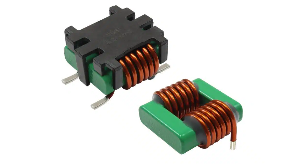
Vishay Intertechnology has introduced the ICMS2321-10 commercial-grade and ICMS2321-1A automotive-grade low-profile common-mode chokes for high-current power-electronics filtering.
The Vishay new series combines heat-rating current up to 30 A, 1500 VDC dielectric withstand voltage between windings, and operation at temperatures up to +150 °C for automotive, industrial, and energy applications.
Key features and benefits
- High-current capability: Vishay specifies heat-rating current from 7 A to 20 A for an approximate 40 °C temperature rise, and 10 A to 30 A for an approximate 100 °C temperature rise.
- High-temperature operation: The chokes are designed for applications with temperatures up to +150 °C, supporting power stages exposed to elevated ambient and self-heating conditions.
- Low-profile, rugged construction: According to Vishay, the low-profile design reduces component size and volume while increasing resistance to shock and vibration.
- High winding-to-winding isolation: A 1500 VDC dielectric withstand voltage between coils supports use on higher-voltage power rails, subject to full system insulation coordination.
- Assembly flexibility: Surface-mount and through-hole termination options are available. SMD versions support automated pick-and-place assembly and tape-and-reel packaging.
- Automotive option: The ICMS2321-1A is AEC-Q200 qualified, making it relevant to automotive programmes that require passive-component qualification evidence.
- Environmental compliance: Both series are RoHS-compliant, halogen-free, and Vishay Green.
A common-mode choke attenuates noise currents flowing in the same direction through both conductors while allowing the intended differential load current to pass with comparatively low impedance. This makes the component particularly useful where high DC current and conducted-EMI control must coexist.
Technical highlights
| Parameter | ICMS2321-10 | ICMS2321-1A |
|---|---|---|
| Grade | Commercial | Automotive |
| Inductance range | 70 µH to 480 µH | 70 µH to 480 µH |
| Typical DCR | 1.2 mΩ to 13.4 mΩ | 1.2 mΩ to 13.4 mΩ |
| Maximum DCR | 1.3 mΩ to 15.0 mΩ | 1.3 mΩ to 15.0 mΩ |
| Common-mode impedance at 1 MHz | 540 Ω to 3790 Ω | 540 Ω to 3790 Ω |
| Common-mode impedance at 10 MHz | 345 Ω to 1920 Ω | 345 Ω to 1920 Ω |
| Common-mode impedance at 100 MHz | 220 Ω to 410 Ω | 220 Ω to 410 Ω |
| Heat-rating current, typical, 40 °C rise | 7 A to 20 A | 7 A to 20 A |
| Heat-rating current, typical, 100 °C rise | 10 A to 30 A | 10 A to 30 A |
| Maximum leakage inductance | 1.7 µH to 11.5 µH | 1.7 µH to 11.5 µH |
| Dielectric withstand voltage between coils | 1500 VDC | 1500 VDC |
| Maximum operating temperature | +150 °C | +150 °C |
| AEC-Q200 qualification | No | Yes |
The impedance values indicate the expected common-mode filtering contribution over frequency, but they should be matched with the measured emissions spectrum rather than treated as a standalone indication of filter performance. Low milliohm-class DCR is also important in multi-ampere rails because it limits conduction loss and associated temperature rise.
Typical applications
Vishay identifies the ICMS2321 series for:
- DC/DC converters
- High-voltage inverters
- EMI filters
- High-current noise-suppression filters
- Motor-control circuitry
- Automotive on-board chargers, particularly for the ICMS2321-1A
- Industrial and energy power-electronics systems operating at elevated temperatures
The series is most relevant at a converter input, output, cable interface, or other boundary where common-mode switching noise can couple onto paired conductors. In motor drives and high-voltage inverter assemblies, the winding-to-winding dielectric withstand rating can be valuable, but it does not replace system-level creepage, clearance, isolation, and transient validation.
Application fit
| Design requirement | ICMS2321 suitability | Engineering consideration |
|---|---|---|
| Multi-ampere DC power rail | Strong fit | Evaluate DCR, continuous current, copper loss, and winding temperature at worst-case ambient conditions |
| High-temperature converter or inverter | Strong fit | Validate the complete thermal stack-up, including PCB, enclosure, airflow, and adjacent heat sources |
| Automotive on-board charger | ICMS2321-1A | Confirm AEC-Q200 documentation, production approval requirements, and application-specific stress conditions |
| EMC filter near a cable interface | Strong fit | Position the choke at the noise boundary and control the filtered/unfiltered layout separation |
| Differential-mode emissions issue | Partial fit | A common-mode choke may need to be combined with X capacitors, a differential inductor, damping, or layout changes |
Design-in notes for engineers
- Use impedance curves, not inductance alone. Common-mode impedance must cover the frequency band where the converter, inverter, cable, or motor system produces the problematic emissions.
- Interpret heat-rating current correctly. Vishay’s current figures are tied to approximate winding temperature rises of 40 °C or 100 °C. The 30 A figure is associated with the higher permitted temperature rise, not necessarily a continuous current rating for every thermal environment.
- Calculate resistive loss in the complete current path. The choke’s low DCR helps reduce loss, but PCB traces, vias, connectors, terminals, and nearby copper restrictions can materially affect total heating.
- Assess saturation under operating conditions. Vishay states that the enhanced core design increases saturation-current performance at high temperature; final verification should nevertheless include the maximum DC bias, transient current, and temperature profile of the specific circuit.
- Separate common-mode and differential-mode noise analysis. A common-mode choke is effective for common-mode current, whereas differential-mode noise may require a different inductor, capacitors, damping network, or switching-layout improvement.
- Protect the PCB filter layout. Keep the choke close to the connector or other relevant noise boundary, minimise the loop area of shunt capacitors, and prevent capacitive coupling between noisy and filtered conductors. These principles are central to effective EMI filter design in power electronics.
- Review leakage inductance where waveform integrity matters. The specified maximum leakage inductance range of 1.7 µH to 11.5 µH should be assessed in circuits sensitive to differential-mode impedance, current ripple, or high-frequency transient behaviour.
- Treat AEC-Q200 as a qualification input, not a complete system approval. The ICMS2321-1A qualification supports automotive passive-component screening; solder-joint reliability, vibration, thermal cycling, insulation coordination, EMC, and supply-chain approval still require system-level validation.
- Confirm the final configuration. Vishay offers custom inductance, impedance, DCR, and current ratings. Engineers should confirm the selected part number, termination style, footprint, magnetic data, qualification status, and availability according to the current manufacturer datasheet.
Further reading
- A Guide to Understanding Common Mode Choke
- Toroidal Inductors, Common Mode Chokes and Beads
- EMI Filters in Power Electronics
- MIL Spec MIL-PRF vs Automotive AEC-Q200 Explained
Source
This article is based on Vishay Intertechnology’s manufacturer press release and official product information for the ICMS2321-10 and ICMS2321-1A common-mode chokes. Engineers should consult the current manufacturer datasheet and associated documentation for final component qualification, thermal assessment, PCB design, and production release.












