











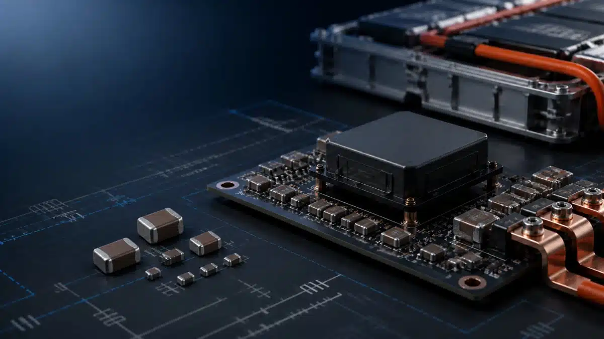
Filter capacitors are essential to controlling conducted electromagnetic interference (EMI) and switching-noise ripple in electric-vehicle battery and power-conversion systems. In high-voltage EV electronics, they can provide line-to-line or line-to-ground noise suppression, or form a controlled high-frequency coupling path across an isolated DC/DC converter barrier.
This article is based on a Knowles manufacturer technical blog covering filter safety capacitors in electric-vehicle battery-management and DC/DC-converter subsystems.
Key features and benefits
- Safety-capacitor topology: Class X capacitors are connected between line and neutral, while Class Y capacitors are connected between line and ground.
- EV-oriented selections: Knowles recommends Class Y2/X1, X1 and X2 capacitors approved for mains AC voltages up to 250 Vac for applicable EV uses.
- High-voltage MLCC option: Multilayer ceramic capacitors can meet tight board-area and elevated-temperature requirements in EV subsystems where conventional ceramic or plastic-film RFI/EMI suppression capacitors may not be suitable.
- BMS and converter coverage: Safety capacitors can be used at a high-voltage battery bus, at cell-module interfaces, in DC/DC converter input filters, and as an isolation-barrier coupling capacitor.
- Noise control: Proper capacitor selection helps control differential-mode and common-mode noise that may otherwise interfere with low-voltage infotainment, sensor and safety systems.
Safety-capacitor subclasses
Class X and Class Y designations define the intended connection point and safety behaviour, while subclasses distinguish the rated mains voltage and impulse-voltage capability. The selection must be based on the complete circuit position and applicable insulation and transient requirements, not on capacitance value alone.
| Capacitor subclass | Rated AC voltage | Peak impulse voltage | Typical connection |
|---|---|---|---|
| X1 | ≤ 480 Vac | 4.0 kV | Line-to-line |
| X2 | ≤ 305 Vac | 2.5 kV | Line-to-line |
| X3 | ≤ 305 Vac | 1.2 kV | Line-to-line |
| Y1 | ≤ 500 Vac | 8.0 kV | Line-to-ground |
| Y2 | ≤ 305 Vac | 5.0 kV | Line-to-ground |
| Y3 | ≤ 250 Vac | Not specified | Line-to-ground |
| Y4 | ≤ 150 Vac | 2.5 kV | Line-to-ground |
In practice, Class X capacitors are intended for line-to-line suppression, where a short-circuit failure is the principal concern. Class Y capacitors are connected to ground or across an isolation boundary, so their safety role also requires careful control of leakage current and insulation coordination.
Technical highlights
| Converter or system location | Capacitor function | Manufacturer example |
|---|---|---|
| High-voltage battery bus / BMS | Line-to-ground EMI control and support for insulation-resistance monitoring arrangements | Class Y safety capacitor |
| Battery cell module | Line-to-line noise suppression | Class X safety capacitor |
| Isolated DC/DC input | Input filtering and switching-noise countermeasure | X7R StackiCap, 250 V to 1.2 kV, 100 nF to 1 µF |
| Isolated DC/DC primary-secondary interface | Common-mode-noise reduction across the isolation barrier | Class Y2 MLCC, 1 kV to 2 kV, 2.2 nF to 4.7 nF |
The StackiCap range cited by Knowles uses an X7R dielectric MLCC ceramic capacitors. This provides a compact filtering option, but effective capacitance under applied DC bias and over the operating-temperature range should be verified for the selected voltage, case size and layout according to the manufacturer datasheet.
BMS filtering arrangement
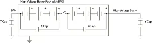
In the illustrated BMS arrangement, Class Y safety capacitors are located at the high-voltage bus, while Class X capacitors are used with individual cell modules to reduce exposure to EMI disturbances. Knowles also indicates that an RC circuit can provide electric-leakage protection through insulation-resistance monitoring of the high-voltage system.
The final selection depends on the vehicle architecture, including whether the BMS is used in an electric bus or a passenger vehicle. Engineers should therefore confirm the voltage distribution, insulation-monitoring method, harness topology, transient environment and applicable safety requirements at system level.
DC/DC converter arrangement
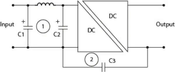
In the isolated DC/DC converter example, C1 and C2 act as EMI-filter or input capacitors that counter switching-noise disturbances at the converter input. Knowles cites an X7R StackiCap option spanning 250 V to 1.2 kV and 100 nF to 1 µF for high-capacitance input-filter duties.
Capacitor C3 connects the primary and secondary ground lines to reduce common-mode noise reaching the secondary side from primary-side switching. Knowles identifies a safety-certified Class Y2 MLCC with 1 kV to 2 kV rating and 2.2 nF to 4.7 nF capacitance as a possible fit, where the required voltage rating corresponds to the transformer insulation voltage.
For related circuit context, see the input-filter design considerations for DC/DC converters and the role of EMI filters in power electronics.
Typical applications
Filter capacitors can serve several EV power-electronics functions:
- High-voltage battery packs and battery-management systems
- Isolated HV-to-12 V and other low-voltage DC/DC converters
- Infotainment, sensing, control and safety-system supply rails
- Conducted-EMI reduction at switching-converter inputs and outputs
- Common-mode-noise suppression across isolated transformer interfaces
- Insulation-resistance monitoring circuits in high-voltage battery systems
Application fit
Safety film capacitors remain established components for RFI and EMI suppression. However, MLCC technology can be particularly relevant where high operating temperature, limited PCB area and small component dimensions are dominant constraints.
The component technology alone does not determine suitability. Designers should verify actual capacitance at the applied DC bias, voltage and surge capability, AC ripple and heating, terminal mechanical stress, creepage and clearance, leakage-current limits, and the complete vehicle-level EMC performance.
Design-in notes for engineers
- Identify the disturbance mode first. Separate differential-mode from common-mode noise before selecting X capacitors, Y capacitors, inductors and damping elements.
- Select the appropriate safety subclass. X and Y subclasses have distinct rated-voltage and impulse-voltage capability; choose the class based on the capacitor’s actual connection and transient exposure.
- Treat C3 as part of isolation design. A primary-to-secondary coupling capacitor needs a voltage rating consistent with transformer insulation and the full insulation-coordination strategy.
- Validate MLCC capacitance at the operating point. An X7R nominal capacitance does not necessarily equal its in-circuit value under DC bias, temperature and AC ripple.
- Evaluate leakage-current constraints. Y-capacitor value selection must balance common-mode attenuation against allowed leakage current.
- Minimise parasitic inductance. Place high-frequency input capacitors close to the switching stage and minimise the loop area of high-di/dt current paths.
- Verify the full system. Test the design with representative harness lengths, grounding arrangements, converter switching conditions and vehicle operating modes.
- Confirm final documentation. The latest manufacturer datasheet should be used to confirm safety approvals, qualification status, test conditions, part-number availability and final ratings.
For safety-topology background, see Safety Capacitors and Safety Class X and Y Capacitors in EVs.
Further reading
- Safety Capacitors
- Safety Class X and Y Capacitors in EVs
- Input Filters for DC/DC Converters
- MLCC Capacitors Applications in Automotive EV Electronics
Source
This article is based on a Knowles manufacturer technical blog covering filter capacitors in electric-vehicle battery-management and DC/DC-converter subsystems. Engineers should consult the current manufacturer datasheet and associated documentation for final component qualification, safety assessment and design release.












