











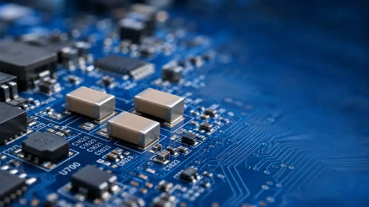
High‑voltage DC systems around 800 V are becoming a mainstream architecture in AI power shelves and other high‑power electronics, driving demand for compact multilayer ceramic capacitors (MLCCs) rated at 1000 V and above.
Samsung Electro‑Mechanics has introduced new C0G and X7 MLCC options targeted at these applications, offering design engineers alternatives to traditional film capacitors in snubber, resonant, and DC‑link stages.
Key features and benefits
High‑voltage rating for 800 V DC rails
- 1000 V rated MLCCs are recommended for use on 800 V DC buses in modern AI power systems, providing sufficient margin for transient overvoltage and ripple.
- The high voltage capability allows direct connection across high‑side nodes, reducing the need for multi‑stage voltage conversion purely for capacitor protection.
C0G dielectric for precision and stability
- C0G MLCCs exhibit negligible capacitance change under DC bias, so even at 800 V DC the capacitance is effectively constant over the specified operating range.
- Temperature dependence from −55 °C to 125 °C is close to zero, which is advantageous in resonant tanks, snubber networks, and precision filters where stable reactance is critical.
- Low dielectric loss leads to low self‑heating, helping maintain reliability in high‑frequency, high‑Q circuits.
X7 series for high volumetric efficiency
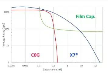
- X7 MLCCs use a high‑ dielectric to achieve high capacitance in relatively small packages, improving volumetric efficiency compared with C0G and many film capacitor options.
- These devices are suitable for power‑stage functions such as input/output smoothing and DC‑link buffering in DC‑DC converters, where bulk capacitance in limited PCB area is a primary requirement.
Trade‑offs versus film capacitors
- Compared with film capacitors, these MLCCs enable significant space savings and facilitate high‑density layouts in power shelves and rack‑level power modules.
- In return, engineers must account for the DC‑bias and temperature characteristics of X7 parts, and the limited maximum capacitance achievable with C0G at 1000 V.
Typical applications
C0G MLCC use cases
- Snubber circuits across high‑voltage switches, where stable capacitance and low loss support predictable damping and reduced overshoot.
- Resonant converters and LLC tanks, where C0G stability helps maintain resonant frequency over operating voltage and temperature.
- High‑precision filters in measurement, sensing, or control circuitry exposed to elevated voltages.
X7 MLCC use cases
- High‑voltage DC‑link smoothing on 800 V DC buses feeding AI compute shelves and power converters.
- Input and output smoothing stages in DC‑DC converters handling high‑power loads, where multiple X7 MLCCs can replace or complement film capacitors.
- General bypass and decoupling at high DC potentials, especially where PCB area is constrained.
System‑level context
- AI systems with power consumption up to the megawatt range require careful management of current and losses; using higher voltage reduces current according to the relationship .
- Conduction losses are proportional to , so reducing current lowers resistive heating, copper cross‑section requirements, and overall system losses.
- Fewer conversion stages between AC and board‑level DC rails simplify the architecture and support miniaturization, making compact, high‑voltage MLCCs more attractive in dense power shelves.
Technical highlights
Dielectric options and characteristics
- C0G MLCCs:
- Extremely stable capacitance versus DC bias, including at 800 V DC.
- Minimal capacitance variation over the −55 °C to 125 °C range.
- Very low dissipation factor (DF), resulting in ultra‑low self‑heating under AC excitation.
- X7 series MLCCs:
- High dielectric constant enabling significantly higher capacitance for a given case size.
- Pronounced DC‑bias effect, with capacitance dropping to roughly 30% of the nominal value under specified DC voltage conditions.
- Additional temperature dependence that must be considered via temperature‑capacitance characteristics (TCC) from the datasheet.
Representative part numbers and sizes
Samsung Electro‑Mechanics highlights the following 1000 V MLCC part numbers:
| Function / dielectric | Part number | Case size (inch) | Capacitance (nominal) | Notes |
|---|---|---|---|---|
| Precision, C0G | CL32C333JIVNNW# | 1210 | 33 nF | Max C0G capacitance at 1000 V in 1210 per manufacturer. |
| Power, X7 | CL43B473KIURPJ# | According to datasheet | 47 nF class (per series indication) | High‑voltage smoothing / bypass; exact values per datasheet. |
| Power, X7 | CL55B104KIURPJ# | According to datasheet | 100 nF class (per series indication) | High‑capacitance DC‑link / smoothing; exact values per datasheet. |
Samsung Electro‑Mechanics is also reviewing a 2220‑size 470 nF 1000 V model as part of its next‑generation portfolio for 800 V DC adoption.
Performance versus operating conditions
- At 1000 V rating, the C0G CL32C333JIVNNW# provides 33 nF maximum capacitance in a 1210 case, which is suitable for high‑frequency, low‑loss functions but not for bulk energy storage.
- X7 parts such as CL43B473KIURPJ# and CL55B104KIURPJ# offer significantly higher capacitance density, at the cost of DC‑bias‑induced derating that must be factored into any energy storage or ripple current calculations.
- For X7 capacitors, designers should always refer to manufacturer DC‑bias and TCC curves at the intended operating voltage and temperature, rather than relying solely on room‑temperature, zero‑bias nominal values.
Design‑in notes for engineers
Choosing between C0G and X7
- For snubber and resonant tank capacitors, prefer C0G parts like CL32C333JIVNNW# when stable capacitance and low loss are more important than achieving very high capacitance.
- For DC‑link and smoothing functions on 800 V DC rails, X7 MLCCs such as CL43B473KIURPJ# and CL55B104KIURPJ# are suitable, provided that circuit calculations use the effective capacitance under DC‑bias and temperature, not just the nominal datasheet value.
- Consider using a mix of C0G and X7 MLCCs where precision and bulk capacitance must coexist, for example a resonant tank in front of a DC‑link stage.
Accounting for DC‑bias and temperature
- Always consult the manufacturer’s DC‑bias and TCC graphs at the intended operating voltage, such as 800 V DC, and expected temperature profile in the equipment.
- For X7 MLCCs, design with the reduced effective capacitance (around 30% of nominal at specified conditions) to avoid under‑dimensioning the DC‑link or smoothing stage.
- Validate hot‑spot temperature and self‑heating through simulation and measurement, especially in high‑frequency converter stages.
Replacing or complementing film capacitors
- In space‑constrained power shelves, clusters of 1000 V MLCCs can reduce volume compared with film capacitors and enable more compact layouts.
- When replacing film capacitors, verify peak current, ripple current capability, and mechanical considerations such as PCB stress, as ceramic parts behave differently under mechanical and thermal cycling.
- Hybrid solutions using both film and MLCC technology can balance energy storage, robustness, and layout flexibility, especially in 800 V DC systems serving AI compute racks.
System‑level design hints
- Higher bus voltages reduce current according to the relationship I=P/V and lower conduction losses proportional to I2R, which should be reflected in conductor sizing and thermal management strategies.
- With fewer conversion stages between AC input and DC loads, ensure that protection, filtering, and transient management are adequate, using appropriate combinations of MLCCs and other passive components.
- For large AI installations approaching megawatt power levels, consider the impact of capacitor technology choice on rack density, serviceability, and long‑term reliability.
Source
This article is based on product news and related technical information published by Samsung Electro‑Mechanics, with technical details interpreted for design engineers and component purchasers according to the manufacturer datasheets and application guidance.












