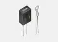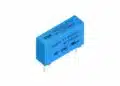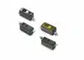


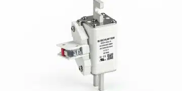



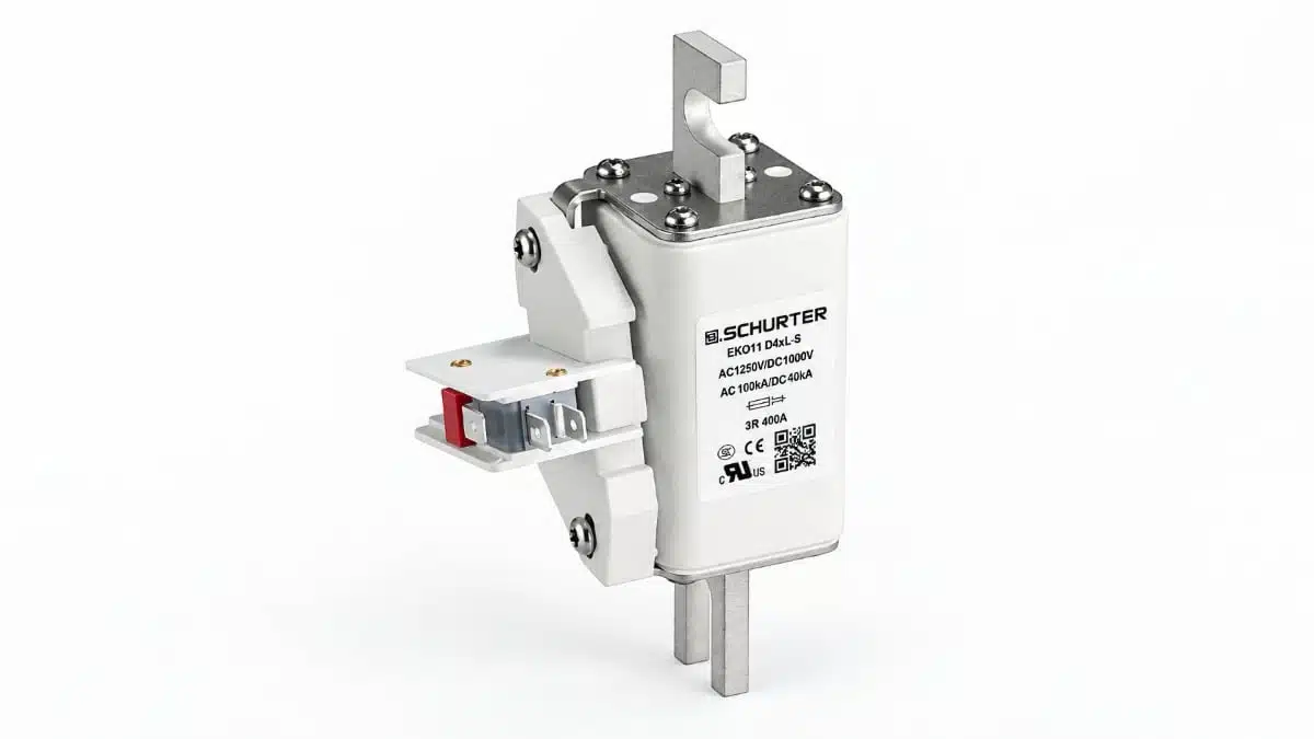
SCHURTER has expanded its EKO square-body high-voltage fuse family with EKO16, EKO41, EKO42, EKO43, EKO44, EKO83 and EKO85 variants.
The additions extend the portfolio to 1500 V DC and 2000 A, with different connection formats for energy storage, EV charging and power conversion equipment. Selection depends on the combination of operating voltage, continuous current, fault-current interruption and mechanical integration.
Key features and benefits
- Rated DC voltages of 500 V, 1000 V and 1500 V across the family, with rated currents from 50 A to 2000 A.
- Additional 1500 V DC options spanning 125 A to 2000 A across several sub-families.
- Breaking capacities up to 250 kA for selected versions, subject to the applicable test conditions.
- Flush-end, DIN-rail, US-style bolted-tag, bolt-on and manual service disconnect mounting concepts.
- Optional indicators and microswitches on selected variants.
- Ceramic bodies and tin-plated copper-alloy terminals.
- Admissible ambient temperature from −40 °C to +125 °C, with current selection governed by temperature derating.
Technical highlights
New sub-families and electrical coverage
The added sub-families divide the voltage and current envelope into distinct selection ranges. The maximum voltage and current ratings belong to particular variants rather than every fuse in the family.
| Sub-family | Rated voltage | Rated current range |
|---|---|---|
| EKO16 | 1500 V DC | 150–300 A |
| EKO41 | 1500 V DC | 250–630 A |
| EKO42 | 1500 V DC | 125–500 A |
| EKO43 | 1500 V DC | 200–630 A |
| EKO44 | 1500 V DC | 1000–2000 A |
| EKO83 | 500 V DC | 160–630 A |
| EKO85 | 1000 V DC | 50–250 A |
EKO44 adds the highest-current 1500 V DC options in this expansion. EKO42 and EKO43 provide overlapping current ranges but differ in physical format and electrical characteristics. EKO83 and EKO85 address lower-voltage requirements with different current ranges and connection arrangements.
Breaking capacity and test conditions
Breaking capacity is separate from rated current. Rated current supports continuous-load selection; breaking capacity governs the prospective fault current the fuse can interrupt under the applicable conditions.
| Sub-family | DC breaking capacity | Test time constant |
|---|---|---|
| EKO16 | 30 kA | 2 ms |
| EKO41 | 50 kA | ≤3 ms |
| EKO42 | 250 kA | 10 ms |
| EKO43 | 250 kA | 10 ms |
| EKO85 | 50 kA | 10 ms |
The test time constant matters alongside the fault-current magnitude. A breaking-capacity value should therefore be evaluated with its voltage and test conditions, rather than treated as an independent headline rating.
For example, EKO42 combines a 1500 V DC rating with 250 kA breaking capacity at a 10 ms time constant. EKO16 also carries a 1500 V DC rating, but its interruption rating is 30 kA at 2 ms. These are different protection envelopes despite the shared rated voltage.
Construction, mounting and standards
The EKO construction combines a ceramic body with tin-plated copper-alloy terminals and a specially developed filler formulation and curing process. Mounting options accommodate different electrical connection and equipment-layout requirements.
The family is designed in accordance with IEC 60269-4, UL 248-13 and GB/T 13539.4. These semiconductor fuse standards concern fuse-links used to protect semiconductor devices. Protection coordination still depends on the selected fuse’s time-current behaviour and I²t characteristics.
Typical applications
Battery energy storage systems
Target positions include battery packs, racks, power conversion systems, sections, modules and power distribution units. The 1500 V DC sub-families provide voltage-rating options for storage architectures within that envelope, while EKO44 extends current selection to 2000 A.
EKO42 and EKO43 offer 250 kA interruption capability at a 10 ms time constant. In these positions, the prospective short-circuit current and circuit time constant are central selection inputs alongside continuous current.
EV charging infrastructure
EV charging is a target application for the EKO family. The additional 1500 V DC variants broaden the voltage and current combinations available for charger protection, while the different terminal formats support alternative equipment connection layouts.
Fuse selection should follow the electrical conditions at the intended installation point. Charger operating current, temporary current excursions and available fault current impose different requirements on the fuse.
Manual service disconnects
EKO83 includes manual service disconnect versions rated at 500 V DC, with current options spanning 160 A to 630 A. The dedicated connection format makes mechanical compatibility with the disconnect assembly part of the initial selection.
Power conversion and industrial equipment
Other target applications include UPS systems, inverters, rectifiers, drives, industrial heaters, welding equipment, metal-processing equipment and data-centre infrastructure.
For power conversion equipment, rated current and breaking capacity address different parts of the protection task. Time-current curves and I²t characteristics must also be coordinated with the protected circuit and its normal operating current profile.
Design-in notes for engineers
- Establish the maximum operating voltage and prospective fault current at the fuse location before choosing a sub-family. Include the DC circuit time constant in the interruption assessment.
- Apply ambient-temperature derating when setting the continuous current. The −40 °C to +125 °C ambient range does not imply unchanged current-carrying capability throughout that range.
- Compare normal current excursions with the selected fuse’s time-current curve. Assess I²t coordination with the protected equipment and other protective devices.
- Include fuse power dissipation in the enclosure thermal budget. For example, the 150 A EKO16 variant has a typical dissipation of 32 W at rated current; the 300 A version has a typical dissipation of 60 W.
- Select the terminal arrangement before fixing the busbar or mounting layout. Use the corresponding outline drawing to establish connection geometry and space for any indicator or microswitch.
- Keep the exact order number tied to the required voltage, current, mounting and indication configuration in the purchasing specification.
- Validate final selection under the actual operating and fault conditions before production release.
Further reading
- Fuse Selection Guidelines
- Fuses for Battery Energy Storage Systems
- Fuse Characteristics and Features
Source
This article is based on the SCHURTER product announcement and official product documentation. Engineers should refer to the current manufacturer datasheet for final design and qualification.
References
- SCHURTER Expands EKO Series for High-Current DC Applications, SCHURTER, 12 October 2026.
- EKO — HV Fuse, up to 1250 VAC / 1500 VDC, up to 2000 A, SCHURTER, 12 October 2026.