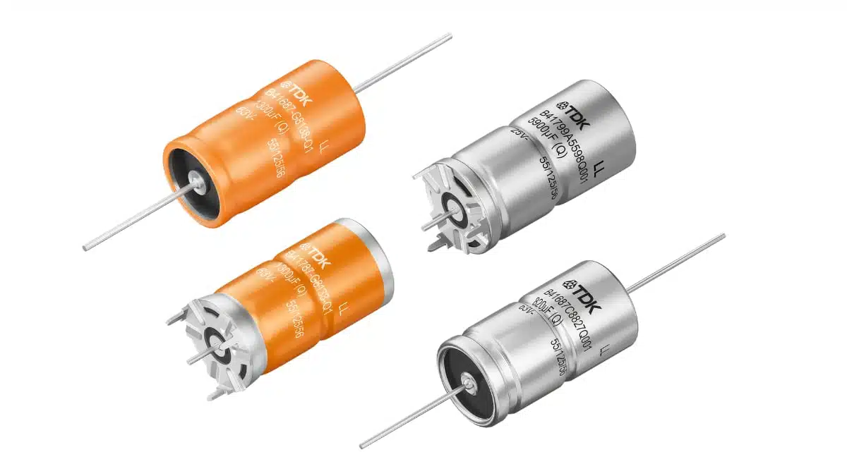
TDK has extended its axial and soldering‑star aluminum electrolytic capacitor portfolio with new 125 V DC‑link types and an upgraded 25–63 V range, targeting compact, high‑ripple DC‑link capacitor banks in demanding environments.
These aluminum electrolytic capacitors address growing needs in micromobility, small xEVs and industrial drives where space, thermal stress and vibration are critical constraints.
Key features and benefits
- Higher DC‑link voltage in a single can – The B43693/B43793 series is now available up to 125 V, extending the family’s coverage from 125 V to 250 V DC links and avoiding the need to stack capacitors in series for typical 96–120 V battery systems.
- Extended low‑voltage range – The B41687/B41787 series covers 25 V to 63 V DC with upgraded 63 V types, giving designers a consistent mechanical platform across low and mid‑voltage DC links.
- High ripple‑current capability – Single capacitors support ripple currents up to 21.6 A, with the option to more than double the rated ripple via optimized heat‑sink mounting according to the manufacturer datasheet. This allows fewer parts per bank and better power density.
- Wide operating temperature range – The 125 V family operates up to +140 °C, and the 25–63 V family up to +150 °C, suitable for tightly packed inverters, automotive ECUs and industrial drives with elevated ambient temperatures.
- Low ESR for efficiency – All four series feature low equivalent series resistance, reducing I²R loss in the DC‑link stage and easing thermal design.
- Mechanical robustness and vibration resistance – Standard vibration resistance is specified up to 20 g, with options up to 60 g on request, making these parts fit for harsh mobile and industrial environments.
- Flexible mounting options – Axial‑lead and soldering‑star terminals support horizontal PCB mounting, vertical mounting and direct busbar attachment, enabling compact layouts in battery and inverter assemblies.
- Space and volume savings – The combination of high ripple current, higher voltage ratings and robust construction enables smaller, lighter capacitor banks, an advantage in micromobility and robotics platforms.
- Compliance and environmental aspects – The series is RoHS‑compatible, supporting modern compliance requirements without special handling measures.
Typical applications
These axial and soldering‑star aluminum electrolytic capacitors are aimed at DC‑link and energy‑buffering roles in compact, vibration‑prone systems where battery voltages range roughly from 48 V to 120 V. Typical use cases include:
- Small xEV traction inverters and on‑board chargers in micromobility platforms.
- DC‑link buffering in industrial inverters for forklifts and warehouse vehicles.
- Power stages in electric boats and other compact marine drives.
- Servo and actuator drives in humanoid robots and robotic manipulators.
- High‑ripple DC‑link stages in modular industrial electronics and distributed power systems.
In these applications, the axial and soldering‑star form factors simplify connection to busbars or compact PCBs, while the vibration ratings and temperature capability support long‑term reliability under shock, vibration and fluctuating load profiles.
Technical highlights
Electrical ratings and ranges
According to the manufacturer press release and datasheet:
- B43693/B43793 series
- Rated voltage range: 125 V to 250 V DC.
- Capacitance range: 56 µF to 650 µF.
- Ripple current: up to 21.6 A, depending on case size and cooling.
- Operating temperature: up to +140 °C.
- B41687/B41787 series
- Rated voltage range: 25 V to 63 V DC.
- Capacitance range: 510 µF to 4800 µF.
- Operating temperature: up to +150 °C.
All four series are described as low‑ESR parts optimized for DC‑link applications. Low ESR directly translates into reduced power loss and lower internal temperature rise for a given ripple current, which is critical when these capacitors are placed close to switching devices.
Mechanical construction and vibration performance
- Axial and soldering‑star terminals enable both horizontal and vertical mounting, and direct connection to busbars or reinforced PCBs.
- Standard vibration resistance is specified up to 20 g, with versions capable of up to 60 g on request. The unit g refers to the acceleration due to gravity, approximately 9.81 m/s², which is a standard way of expressing vibration severity.
- Can sizes range from 16 × 25 mm to 21 × 49 mm (diameter × length) for the 125 V variants, offering a spectrum of compact form factors tailored to different power levels and layout constraints.
This mechanical robustness is particularly relevant for mobile systems such as forklifts or small EVs, where the DC‑link capacitor bank is exposed to continuous vibration and occasional shocks.
Ripple‑current optimization with heat‑sink mounting
The press release highlights that carefully mounting the 125 V series to a heat sink can more than double the permissible ripple current. An example is given for an 18 × 30 mm can:
- At +105 °C ambient, the standard ripple current rating is 5.2 A.
- When the aluminum case is held at +105 °C via a heat sink, the permissible ripple current rises to 11.1 A, effectively more than doubling the usable ripple capability for that footprint.
From a design‑in perspective, this means mechanical integration and thermal coupling can be used as active design levers to reduce capacitor count and cost in the DC‑link, provided that the thermal interface between the can and heat sink is carefully engineered.
Overview of key series parameters
Table 1 – Overview of TDK axial/soldering‑star aluminum electrolytic series for DC‑link
| Series | Voltage range (DC) | Capacitance range | Max temperature | Typical use in DC‑link |
|---|---|---|---|---|
| B43693 | 125–250 V | 56–650 µF | up to +140 °C | Higher‑voltage DC‑link, 96–120 V battery packs |
| B43793 | 125–250 V | 56–650 µF | up to +140 °C | Similar range, alternative mechanical versions |
| B41687 | 25–63 V | 510–4800 µF | up to +150 °C | Low‑voltage DC‑link and buffer stages |
| B41787 | 25–63 V | 510–4800 µF | up to +150 °C | Matching form factor for standardized designs |
Exact rated values and tolerance classes for individual part numbers should be taken from the manufacturer datasheet.
Design‑in notes for engineers
- Match battery voltage and DC‑link margin
For small xEVs and micromobility platforms with nominal 48–120 V battery systems, the 125 V types in the B43693/B43793 series allow direct DC‑link implementation without series stacking. This simplifies balancing and reduces failure risk associated with unequal voltage sharing. - Exploit thermal coupling for fewer parts
When space is tight, consider mechanically coupling the capacitor cans to a heat sink or cooled chassis region. As the example shows, maintaining the can at the specified case temperature can more than double the allowable ripple current, enabling downsizing of the capacitor bank and reducing assembly effort. - Account for vibration early in layout
In mobile and robotic systems, vibration levels can exceed typical industrial environments. The specified vibration resistance up to 20 g, and optional 60 g variants, should be cross‑checked against measured platform vibration spectra. Layouts should avoid cantilevered mounting and ensure solid mechanical support for axial or soldering‑star terminals. - Balance capacitance and ESR for control stability
DC‑link design is not only about capacitance; the ESR influences damping of current ripple and control loop behavior. The low ESR of these series is beneficial for efficiency, but designers may need to add damping elements or tailor control parameters accordingly in very low‑ESR designs. - Use the high‑temperature capability to free PCB space
With operating temperatures specified up to +140 °C and +150 °C depending on the series, these capacitors can be placed closer to power semiconductors and magnetics, freeing up cooler PCB areas for sensitive control electronics. Thermal simulations and measurements should still confirm that local hot spots remain within datasheet limits. - Standardize across voltage classes
The shared axial/soldering‑star construction between B41687/B41787 and B43693/B43793 allows platform designs that reuse mechanical fixtures and assembly processes across both low and high‑voltage variants. This can simplify manufacturing and reduce stock variety. - Consider lifetime vs operating point
Useful life figures such as 2500 h at +125 °C are reference points rather than fixed guarantees for all conditions. Lifetime strongly depends on actual ripple current, temperature and voltage. For long‑life industrial systems, derating and thermal management are essential to achieving desired lifetimes.
Source
This article is based on information from a TDK Corporation press release on axial and soldering‑star aluminum electrolytic capacitors and associated official product information from the manufacturer website and datasheets.