











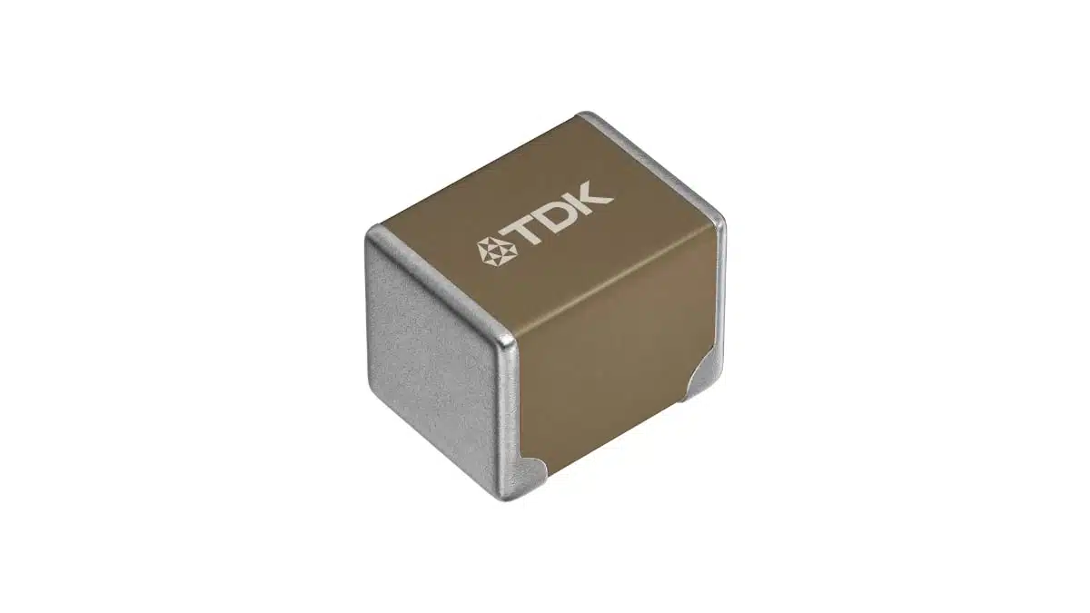
TDK has expanded its CN series of low-resistance soft-termination multilayer ceramic capacitors with new 10 µF, 100 V X7R parts in the 3225 metric case size.
The TDK MLCC capacitors targets smoothing and decoupling on 48 V power lines in AI servers, humanoid robots, xEVs, and industrial equipment, where board-flex robustness and installed capacitance density must be considered together.
Key features and benefits
- 10 µF nominal capacitance at 100 VDC in a 3.2 mm × 2.5 mm × 2.5 mm package, designated EIA 1210.
- X7R dielectric, with a published temperature characteristic of ±15% across the specified temperature range.
- Soft termination intended to reduce transfer of external mechanical stress from the PCB and solder joints into the ceramic body, an important consideration for MLCC ceramic capacitors mounted on large, flexing, or thermally cycled boards.
- Low-resistance terminal construction: TDK states that its optimized resin-electrode structure provides terminal resistance equivalent to its regular terminal products.
- Two released variants are listed: CNA6P1X7R2A106K250AE for automotive-grade applications and CNC6P1X7R2A106K250AE for commercial applications.
- The CNA automotive version is listed as AEC-Q200 qualified. This is a passive-component stress-test qualification, not a complete vehicle-level approval; application-specific validation remains necessary.
- TDK lists both part numbers with production status.
Technical highlights
| Parameter | CNA6P1X7R2A106K250AE | CNC6P1X7R2A106K250AE |
|---|---|---|
| Product grade | Automotive | Commercial |
| AEC-Q200 | Yes | No |
| Rated capacitance | 10 µF | 10 µF |
| Capacitance tolerance | ±10% | ±10% |
| Rated voltage | 100 VDC | 100 VDC |
| Dielectric / temperature characteristic | X7R, ±15% | X7R, ±15% |
| Operating temperature range | -55 °C to +125 °C | -55 °C to +125 °C |
| Case size | 3.2 × 2.5 × 2.5 mm | 3.2 × 2.5 × 2.5 mm |
| Dissipation factor, maximum | 5% | 5% |
| Insulation resistance, minimum | 10 MΩ | 10 MΩ |
| Mounting method | Reflow | Reflow |
TDK specifies length, width, and thickness tolerances of +0.40/-0.30 mm for both parts. The published recommended land-pattern ranges are 2.00 mm to 2.40 mm for PA, 1.00 mm to 1.20 mm for PB, and 1.90 mm to 2.50 mm for PC; the terminal width is specified as 0.50 mm minimum.
The nominal 10 µF value is only one part of the selection calculation. As an X7R Class II MLCC, usable capacitance should be verified at the actual DC voltage, AC ripple, temperature, and lifetime condition; see MLCC DC bias and ageing capacitance loss explained.
Typical applications
TDK identifies the new CN-series types for smoothing and decoupling on 48 V rails in:
- AI servers and associated power-distribution hardware
- Humanoid robots
- xEV electronic and power systems
- Industrial equipment used within the AI ecosystem
For a 48 V distribution rail, a 100 V-rated MLCC can provide voltage-rating margin relative to nominal bus voltage. However, the voltage rating must still be checked against startup events, ringing, cable-induced transients, load-dump exposure where applicable, protection-circuit behaviour, and credible fault conditions.
Application fit
The announcement is relevant where designers need substantial local ceramic capacitance on a higher-voltage low-impedance rail but also need mechanical-stress mitigation. TDK states that the new 10 µF part provides twice the capacitance of its conventional capacitors of the same size, potentially allowing a reduction in the number of MLCCs used in a mounting area.
Reducing the capacitor count can simplify placement and reduce total pad count, but it also changes the impedance network, current sharing, local thermal distribution, and consequences of an individual component failure. A one-for-one replacement should therefore not be assumed without confirming impedance and transient response in the final circuit.
The manufacturer does not publish a direct numerical ESR value, impedance curve, ripple-current limit, or side-by-side comparison with a specific predecessor in the announcement. These values should be confirmed in the current manufacturer datasheet, characteristic data, and applicable design tools before release.
Design-in notes for engineers
- Use bias-dependent capacitance data. Check the TDK DC-bias characteristic at the actual rail voltage and expected temperature, rather than designing around the 10 µF nameplate value.
- Evaluate the complete capacitor bank. Verify output impedance, anti-resonance, control-loop stability, ripple-current distribution, and conducted/radiated EMC with the final number and placement of capacitors.
- Confirm transient stress. A 100 VDC rating does not independently establish suitability for repetitive switching overshoot, surge events, abnormal operating modes, or vehicle transients.
- Apply the recommended land pattern and reflow profile. Soft termination addresses external mechanical stress but does not remove the need for controlled PCB layout, panel handling, solder-joint quality, and assembly-process validation.
- Check board-bending exposure. Place large 3225 MLCCs away from high-strain areas such as mounting holes, connectors, PCB edges, board break-off locations, and heavy components. Soft termination in passive components is one measure within a broader mechanical-reliability strategy.
- Separate automotive and commercial BOM options. Use the CNA version where AEC-Q200 qualification is a project requirement; the CNC version is listed by TDK as commercial grade and is not AEC-Q200 qualified.
- Validate in the assembled system. Confirm electrical performance after reflow and under final mechanical, thermal, humidity, vibration, and power-cycling conditions. Component qualification does not replace module- or system-level validation.
- Control the exact ordering code. Confirm current product status, packaging, approved manufacturer list status, and documentation revision before schematic, PCB-layout, and production release.
Further reading
- MLCC and Ceramic Capacitors
- MLCC DC BIAS and AGEING Capacitance Loss Explained
- Temperature, Bias and Ageing Impact to MLCC Ceramic Capacitors
- MIL Spec MIL-PRF vs Automotive AEC-Q200 Explained
Source
This article is based on the TDK manufacturer press release and the current TDK Product Center entries for the announced part numbers. Engineers should consult the current manufacturer datasheet, specification document, characteristic data, and application documentation for final component qualification and design release.












