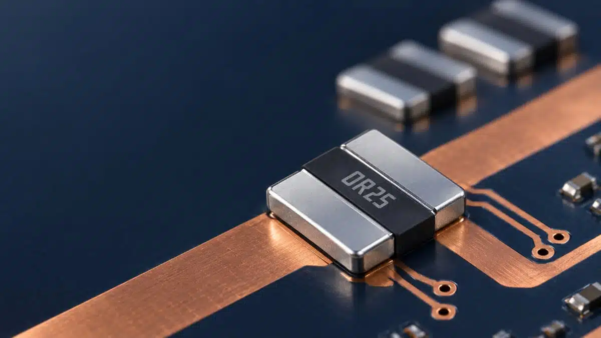
Bourns has released the CRK2725 series of surface-mount metal-strip current-sense resistors for low-resistance power-current measurement.
The new series combines a 5 W rating at 70 °C with 0.2 mΩ to 1 mΩ resistance values, a wide-terminal format and specified low inductance for high-current power paths.
Key features and benefits
- Metal-strip, wide-terminal current-sense resistor series in a 2725 case format
- 5 W power rating at 70 °C
- Resistance range from 0.2 mΩ to 1 mΩ
- ±1% and ±5% resistance tolerances
- ±100 ppm/°C temperature coefficient of resistance
- −55 °C to +170 °C operating temperature range
- Specified inductance below 5 nH
- Specified thermal EMF below 40 μV/°C
- RoHS compliant and halogen free
- Insulation resistance above 100 MΩ
The wide-terminal construction is intended to spread current and heat through a broader PCB contact area. In a low-milliohm shunt, this can reduce the influence of terminal resistance and improve heat transfer into the board, but installed performance still depends strongly on copper area, pad geometry and surrounding heat sources.
Technical highlights
| Parameter | CRK2725 specification | Selection relevance |
|---|---|---|
| Power rating | 5 W at 70 °C | Board thermal design |
| Resistance range | 0.2 mΩ to 1 mΩ | Sense-voltage versus loss trade-off |
| Resistance tolerance | ±1%, ±5% | Initial measurement accuracy |
| TCR | ±100 ppm/°C | Temperature-related gain error |
| Operating temperature | −55 °C to +170 °C | High-temperature power stages |
| Inductance | <5 nH | Switching-current measurement |
| Thermal EMF | <40 μV/°C | Low-level sensing offset |
| Insulation resistance | >100 MΩ | Isolation integrity check |
| Maximum working voltage | V | Must be checked per value |
At the lowest 0.2 mΩ value, the series minimizes insertion loss but produces a correspondingly low sense voltage. The current-sense amplifier’s offset, gain error, input noise and ADC resolution therefore need to be included in the full measurement-error budget.
The ±100 ppm/°C TCR also matters in systems with wide load or ambient-temperature variation. Resistance rises or falls with shunt temperature, so a design that requires accurate current limiting or energy metering should assess the combination of initial tolerance, TCR, self-heating and thermal gradients across the PCB.
Typical applications
The published applications are current sensing, power supplies, stepper-motor drives and input amplifiers.
| Application | Published supporting characteristics | Circuit position |
|---|---|---|
| Power supplies | 5 W at 70 °C, 0.2–1 mΩ | Input or output current shunt |
| Stepper-motor drives | −55 °C to +170 °C, <5 nH | Phase-current measurement |
| Current measurement | ±1% tolerance, ±100 ppm/°C TCR | Feedback or protection loop |
| Input amplifiers | <40 μV/°C thermal EMF | Low-level differential sensing |
In switched-mode power supplies, the low resistance range suits high-current input, output or synchronous-switch current measurement where dissipation must be constrained. The sub-5 nH inductance specification is also relevant when the shunt waveform contains fast switching edges, although the amplifier common-mode range, input filtering, blanking time and PCB loop inductance remain system-level design constraints.
For motor drives, the 5 W rating and +170 °C upper operating-temperature limit support use in high-current phase or supply-return paths. Motor-stall, regenerative and short-circuit conditions must still be checked against the current and pulse capability published for the exact selected resistance value; no separate pulse-load curve or reliability report was located in the public material reviewed for this release.
Design-in notes for engineers
- Use Kelvin sensing and shunt-resistor layout practices where measurement accuracy matters. Route the sense pair from the inner regions of the resistor pads, separately from the high-current copper path.
- Calculate continuous dissipation at worst-case current using , then allow for the actual PCB temperature, nearby MOSFETs, inductors, airflow and enclosure conditions.
- Treat the 5 W figure as a rating at 70 °C, not as a guaranteed dissipation level for every land pattern and copper area. Thermal validation should be performed on the final assembly.
- Check the resistance tolerance and TCR against the complete current-measurement budget, including amplifier offset, gain error, ADC uncertainty and temperature drift.
- Verify the maximum working-voltage relationship, V, for the selected resistance value rather than applying a single voltage assumption across the range.
- Review start-up, inrush, motor-stall, short-circuit and regenerative events separately from steady-state dissipation. The public announcement does not provide pulse-energy or overload curves for CRK2725.
- Keep copper spreading and terminal geometry thermally symmetrical where low offset is important. Unequal terminal temperatures can add thermoelectric error despite the specified low thermal EMF.
- Confirm solder land pattern, assembly profile, derating behaviour and current production status in the current Bourns documentation before schematic, PCB-layout or production release.
Further reading
- Current Sense Shunt Resistor
- How to Choose Current Sense Resistor
- Challenges Using Sub-Milliohm SMD Current Sense Chip Resistors
- SMD Chip Resistors: Types, Packages, Ratings and Design Guide
Source
This information is based on the Bourns CRK2725 product release and publicly indexed official Bourns product documentation. Engineers should consult the current manufacturer datasheet and any applicable mounting, derating, pulse-load and qualification documentation for final qualification and design release.