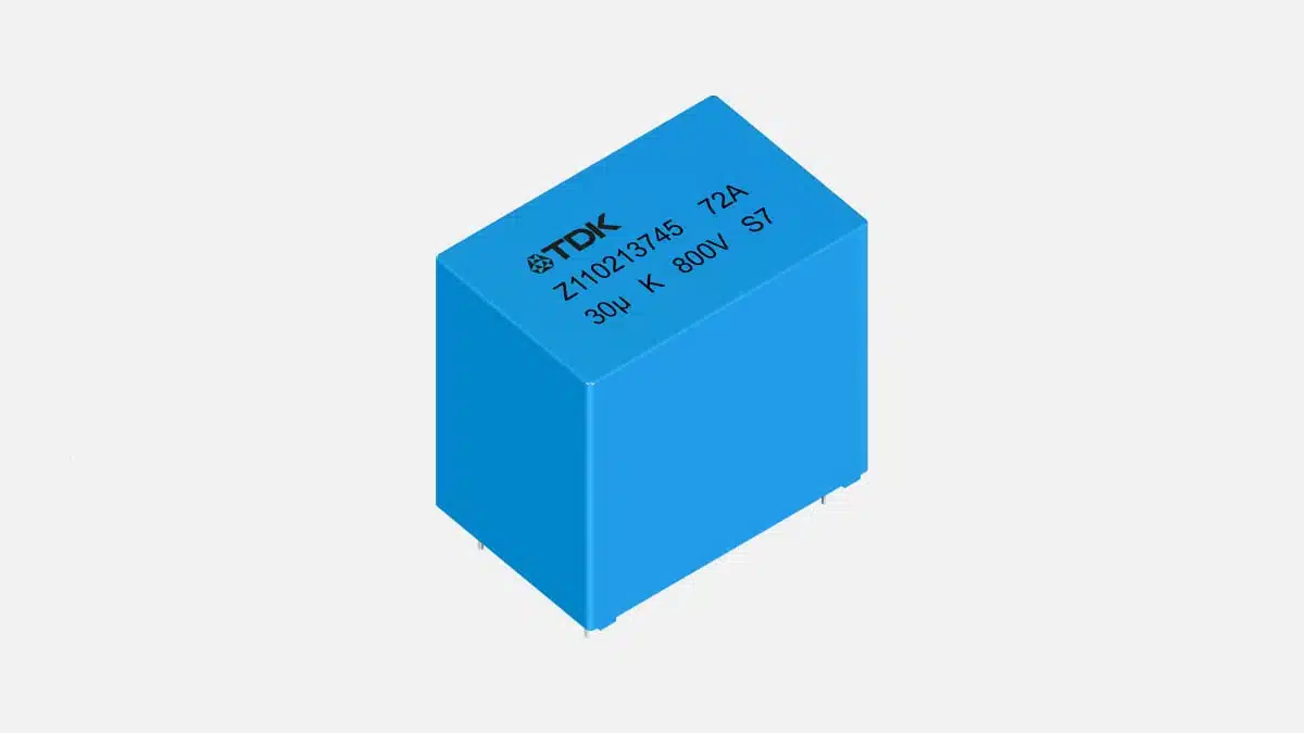
TDK has expanded its radial DC-link film-capacitor portfolio with the B3272*A/G/T series for automotive and industrial power converters.
The new range of TDK DC-link film capacitors combines 800 V DC to 1200 V DC ratings, capacitance values from 1 µF to 60 µF, and case-temperature operation up to +135 °C, addressing designs where thermal margin, ripple-current capability and PCB height are all constrained.
Key features and benefits
- EPN dielectric technology is new for this B3272*A/G/T family. The current series datasheet, revised June 2025, identifies the construction as polypropylene (MKP), while the September 2026 product announcement describes the dielectric as an EPN blend of polypropylene and cyclic olefin copolymer. The current datasheet is followed for all electrical, thermal and mechanical values.
- Rated voltage spans 800 V DC, 900 V DC, 1000 V DC and 1200 V DC.
- Available capacitance spans 1 µF to 60 µF, depending on voltage rating and lead-spacing family.
- Continuous operating voltage equals the rated voltage up to +105 °C. Above this point, voltage derating is required.
- The maximum specified operating temperature is +135 °C case temperature.
- The series is compliant with AEC-Q200 Rev. E and referenced to IEC 60384-16:2019.
- Biased-humidity testing is specified at +60 °C, 95% RH, rated voltage and 1000 hours.
- The plastic case and epoxy-resin sealing meet UL 94 V-0.
- Capacitance tolerance options are ±5% and ±10%.
- The specified service life is 100,000 hours at rated voltage and +85 °C.
- Two-pin A and T variants suit conventional PCB mounting. Four-pin G variants provide parallel wire leads intended to reduce connection inductance compared with a two-lead connection of equivalent geometry.
- The B32726T is the low-profile sub-family, with a 15 mm to 19 mm case-height range.
Technical highlights
The B3272*A/G/T range comprises five mechanical variants: B32724A, B32726A, B32726T, B32726G and B32728G. They use 27.5 mm, 37.5 mm or 52.5 mm lead spacing, with lead diameters from 0.8 mm to 1.2 mm.
| Series | Pins | Lead spacing | Capacitance range | Case-height range |
|---|---|---|---|---|
| B32724A | 2 | 27.5 mm | 1 µF to 12 µF | 19 mm to 36.5 mm |
| B32726A | 2 | 37.5 mm | 2 µF to 12 µF | 22 mm to 32.5 mm |
| B32726T | 2 | 37.5 mm | 2.7 µF to 9 µF | 15 mm to 19 mm |
| B32726G | 4 | 37.5 mm | 6 µF to 40 µF | 37 mm to 48 mm |
| B32728G | 4 | 52.5 mm | 20 µF to 60 µF | 45 mm to 50 mm |
The specified maximum RMS-current range at +85 °C and 10 kHz extends from 3.5 A to 24 A across the family. This current rating is conditional: the tables use a maximum temperature rise of 20 K and a typical ESR variation of no more than ±5%. It is therefore not a universal current limit for arbitrary frequency, waveform, cooling or ambient conditions.
| Parameter | Value | Selection relevance |
|---|---|---|
| Rated voltage | 800 V DC to 1200 V DC | DC-bus operating voltage |
| Capacitance | 1 µF to 60 µF | Energy storage and bus support |
| Operating temperature | Up to +135 °C case | Thermal headroom |
| No-derating voltage region | Up to +105 °C | Full rated-voltage operation |
| Capacitance tolerance | ±5% or ±10% | Bus-capacitance margin |
| RMS current | 3.5 A to 24 A | Ripple-current assessment |
| Test voltage | 1.5 × rated voltage, 10 s | Production and insulation testing |
| Service life | 100,000 h at rated voltage, +85 °C | Lifetime modelling input |
At +125 °C, the continuous operating-voltage limits are 570 V DC, 645 V DC, 720 V DC and 870 V DC for the 800 V DC, 900 V DC, 1000 V DC and 1200 V DC classes respectively. At +135 °C, the respective limits are 440 V DC, 495 V DC, 550 V DC and 665 V DC.
This distinction is central to selecting a high-temperature DC-link capacitor: +135 °C is the maximum operating case temperature, not a condition at which full rated voltage remains available. The voltage-temperature derating must be included in the converter’s worst-case bus-voltage analysis.
The datasheet also specifies isolated-pulse limits. These range from 40 V/µs to 100 V/µs for B32724 types, 25 V/µs to 65 V/µs for B32726 types, and 15 V/µs to 28 V/µs for B32728 types, depending on rated voltage. The limits are defined for isolated pulses where the heat from one pulse is fully dissipated before the next pulse; they must not be used directly as a repetitive switching-waveform rating.
Typical applications
The datasheet supports use in frequency converters, industrial and high-end power supplies, and automotive DC-DC converters and compressors. The press release additionally names xEV traction inverters and on-board chargers as target applications.
- Automotive DC-DC converters and electric compressors: The 800 V DC to 1200 V DC rating range, AEC-Q200 Rev. E compliance, +135 °C maximum case-temperature rating and +60 °C/95% RH/rated-voltage humidity test support use in thermally demanding automotive power-electronics locations.
- Industrial frequency converters: The 1 µF to 60 µF capacitance range, ripple-current capability at +85 °C and voltage options to 1200 V DC support local DC-link capacitor functions in converter assemblies.
- High-end industrial power supplies: The two-pin and four-pin choices allow a trade-off between board-height constraints, capacitance requirement and connection geometry. The low-profile B32726T is relevant where enclosure height is limited.
- Fast-switching inverter stages: Four-pin B32726G and B32728G variants offer a connection format that can help minimise loop area when placed appropriately in the bus structure. The final benefit depends on the complete PCB or busbar geometry, not the capacitor lead count alone.
- Traction inverters and on-board chargers: TDK identifies these as intended DC-link applications in the product announcement. Their final suitability must be established from the selected part’s voltage-temperature derating, RMS-current spectrum, pulse conditions, thermal environment and mechanical mounting arrangement.
Application fit
| Application | Published supporting ratings | Key validation point |
|---|---|---|
| Automotive DC-DC converter | 800 V to 1200 V DC; AEC-Q200 Rev. E; +135 °C case | Voltage derating above +105 °C |
| Electric compressor | +60 °C/95% RH/VR, 1000 h test | Humidity and local self-heating |
| Industrial frequency converter | 1 µF to 60 µF; 3.5 A to 24 A at +85 °C, 10 kHz | Actual ripple-current spectrum |
| High-end power supply | Two-pin and four-pin packages; 15 mm to 50 mm height | Layout inductance and enclosure height |
| Fast-switching inverter DC link | Four-pin G variants; specified impedance and ESR curves | Complete commutation-loop inductance |
AEC-Q200 Rev. E compliance is a component-level stress-test qualification. It does not constitute vehicle-level approval, converter qualification, or validation of the completed system in its installed environment.
Design-in notes for engineers
- Select voltage from the highest simultaneous bus voltage and capacitor operating temperature. A 1200 V DC type is limited to 870 V DC continuous operation at +125 °C and 665 V DC at +135 °C.
- Use the case-temperature definition correctly. The maximum operating temperature is specified as , representing ambient temperature plus capacitor self-heating.
- Calculate ripple losses from the waveform spectrum and the selected part’s ESR versus frequency. The 10 kHz RMS-current table values are not interchangeable with ratings at other frequencies.
- Check the permissible current-versus-frequency and current-versus-temperature curves for the selected voltage and mechanical family.
- Assess self-heating with the datasheet’s specified equivalent heat coefficient, , for the actual capacitor dimensions. The datasheet defines dissipation as and temperature rise as .
- Maintain the thermal margin between ambient temperature, internally generated losses and the +135 °C maximum case-temperature limit.
- Validate repetitive switching stresses separately from the isolated-pulse values. The datasheet expressly limits those pulse figures to conditions allowing thermal recovery between pulses.
- Use the four-pin variants with a low-inductance interconnect strategy. Long, asymmetric traces or busbars can negate the intended reduction in commutation-loop area.
- Include DC-bus overvoltage conditions. The datasheet allows specified overload levels only for limited durations, including 1.1 × rated voltage for 30% of on-load duration, 1.15 × rated voltage for 30 minutes, 1.2 × rated voltage for five minutes and 1.3 × rated voltage for one minute.
- Observe mounting and soldering constraints. These are leaded film capacitors and are not suitable for reflow soldering. For manual or selective soldering, the capacitor-body temperature must remain at or below +120 °C.
- Verify capacitance, ESR, RMS current, voltage derating, lifetime and mechanical stress under final operating conditions before schematic, layout and production release.
Further reading
- TDK Released Robust DC Link Film Capacitors
- TDK Introduces DC link Capacitor for xEV Traction Inverters
- TDK Releases Low Self-Inductance DC Link Film Capacitors
Source
This information is based on the TDK press release and official TDK product documentation for the B3272*A/G/T DC-link capacitor series. Engineers should consult the current manufacturer datasheet and associated documentation for final component qualification, thermal modelling, assembly-process definition and design release.
References
- TDK Electronics, “TDK presents DC-link capacitors rated for up to +135 °C in automotive and industrial applications,” September 30, 2026
- TDK Electronics, “Capacitors for DC Link — B3272A/G/T,” datasheet, June 2025
- TDK Electronics, “Capacitors for DC Link” product catalogue
- TDK Electronics, “The New ModCap Likes It Hot,” January 15, 2026