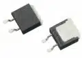









YAGEO Group has introduced the PMT6709NLT and PHT7249NLT SMD transformers for isolated LLC bias supplies used with SiC and GaN switching devices.
The YAGEO two GDSC-series SMD transformers combine reinforced-insulation capability, extended creepage distances and low interwinding capacitance in a compact UI5 platform for high-voltage inverter and motor-drive gate-drive circuits.
Key features and benefits
- PMT6709NLT and PHT7249NLT are gate-drive transformers for LLC converter arrangements supplying positive and negative SiC or GaN gate-drive voltages.
- The platform supports transformer power of up to 3 W.
- Operating temperature is specified from −40 °C to +125 °C.
- The package envelope is 17.2 × 11 × 8.5 mm maximum.
- A two-section bobbin structure keeps interwinding capacitance low while providing leakage inductance that can form part of the LLC resonant network.
- The product documentation identifies the parts as automotive ready, while also explicitly stating that AEC-Q200 qualification testing has not been completed. This distinction matters: automotive-ready positioning and passive-component qualification are not equivalent.
- YAGEO positions the platform for high-frequency SiC/GaN drive circuits, including EV charging, inverters, motor drives and power supplies. The published electrical data most directly support its use as an isolated low-power gate-bias transformer rather than as a main power-conversion transformer.
Technical highlights
| Parameter | PMT6709NLT | PHT7249NLT |
|---|---|---|
| Transformer power | Up to 3 W | Up to 3 W |
| Operating temperature | −40 °C to +125 °C | −40 °C to +125 °C |
| Maximum package | 17.2 × 11 × 8.5 mm | 17.2 × 11 × 8.5 mm |
| Turns ratio | 1:3 | Refer to current datasheet |
| Interwinding capacitance | 2.5 pF | 2.5 pF |
| Leakage inductance | 3.45 µH | 1.4 µH |
| Hi-pot voltage | 3750 Vrms | 4200 Vrms |
| Rated voltage basis | Refer to datasheet | Up to 1250 Vpk |
The latest datasheet differs from the original launch-page summary in several important details. The launch material describes a 10 mm-creepage UI5 platform and isolation voltage up to 4.5 kVrms; the current datasheet gives 12 mm creepage, 7.4 mm clearance and a maximum 4.2 kVrms hi-pot rating for the stated parts. This article therefore follows the current datasheet values.
For PMT6709NLT, the creepage and clearance data are stated for pollution degree 2, overvoltage category II and 2000 m altitude. Under those conditions, the datasheet lists 450 Vrms reinforced insulation and 900 Vrms basic insulation for material group III. The transformer’s insulation rating must be checked against the actual pollution degree, altitude, working voltage, transient environment and insulation class required by the end equipment.
The PHT7249NLT’s stated peak-voltage rating is based on a positive partial-discharge test with discharge below 10 pC under IEC 60664. Partial-discharge testing is relevant because it evaluates insulation-barrier behaviour under repetitive peak voltage; it is not a substitute for verifying the complete converter insulation system.
Typical applications
The documented circuit use is an isolated LLC gate-drive bias supply for SiC and GaN MOSFET switching stages. In this arrangement, the transformer provides galvanic isolation and can generate separate positive and negative secondary outputs for reliable turn-on and turn-off of a high-voltage switch.
- Traction and industrial inverters: The −40 °C to +125 °C operating range, reinforced-insulation provisions and high-voltage isolation support isolated bias supplies within inverter gate-drive assemblies.
- Motor drives: Low 2.5 pF interwinding capacitance reduces the capacitive path for common-mode current between the high-voltage power stage and the control-side bias supply.
- EV chargers and high-voltage DC/DC systems: The up-to-3 W power level suits auxiliary gate-drive power rather than the main energy-transfer stage.
- High-frequency SiC and GaN switching: The two-section bobbin and LLC topology allow the specified leakage inductance to be used as resonant inductance, subject to confirmation against the controller operating range and the intended resonant capacitor.
Low interwinding capacitance is especially relevant in high- switching systems. Displacement current through the transformer capacitance can couple switching noise into the isolated supply and controller ground reference. The published 2.5 pF value helps reduce that coupling path, but common-mode current and conducted or radiated EMI remain dependent on the complete PCB layout, isolation capacitances, switching edge rate, heatsink coupling and cable environment.
Application fit
| Circuit position | Published support | Selection implication |
|---|---|---|
| Isolated gate-bias supply | Up to 3 W, LLC circuit example | Check output-voltage and gate-charge budget |
| SiC/GaN inverter drive | 2.5 pF capacitance, high isolation | Assess common-mode current and CMTI |
| Motor-drive control supply | −40 °C to +125 °C range | Validate winding temperature in enclosure |
| Resonant gate-drive converter | 1.4 µH or 3.45 µH leakage inductance | Match tank values and controller range |
| Reinforced-isolation barrier | PMT: 450 Vrms reinforced basis | Confirm system insulation conditions |
The leakage inductance is not merely a parasitic to minimise in the intended LLC circuit. For the PMT6709NLT, the datasheet lists 3.45 µH; for the PHT7249NLT, it lists 1.4 µH. These values materially affect resonant-frequency selection, gain characteristics and circulating current. The transformer should therefore be selected together with the resonant capacitor, switching-frequency range, gate-drive output-voltage requirement and required startup behaviour.
The documentation illustrates compatibility with Texas Instruments’ UCC25800-Q1 LLC controller. That reference is a circuit example, not confirmation that either transformer is automatically suitable for every controller configuration or gate-driver supply requirement.
Design-in notes for engineers
- Confirm the complete gate-drive power budget, including gate charge, switching frequency, driver quiescent current, secondary regulation requirements and any negative-bias load.
- Select the resonant capacitor and operating-frequency range using the specific transformer leakage inductance. Verify gain and circulating current across input-voltage, load and temperature limits.
- Check the applicable insulation standard at the system level. The stated creepage, clearance and working-voltage figures are conditional on the datasheet’s insulation assumptions.
- Treat hi-pot voltage and repetitive peak-voltage capability as different parameters. A short-duration dielectric withstand test does not by itself define continuous working-voltage capability.
- Evaluate common-mode current with the actual SiC or GaN switching waveform. Transformer capacitance is only one coupling path in the converter.
- Apply the recommended land pattern, soldering profile and mechanical clearances from the current manufacturer documentation before PCB release.
- Validate winding temperature, core loss and copper loss at the final switching frequency. The datasheet notes that applied volt-seconds may require further derating at frequencies above the conditions used for its core-loss and temperature-rise calculation.
- Do not claim AEC-Q200 qualification for the current parts. The current datasheet says that qualification testing has not been completed, even though the launch material describes compatibility with AEC-Q200 qualification requirements.
Further reading
Source
This information is based on the YAGEO Group product announcement and official product documentation for the PMT6709NLT and PHT7249NLT gate-drive transformers. Engineers should consult the current manufacturer datasheet and applicable insulation, qualification and system-level design documentation before final schematic, PCB-layout or production release.