


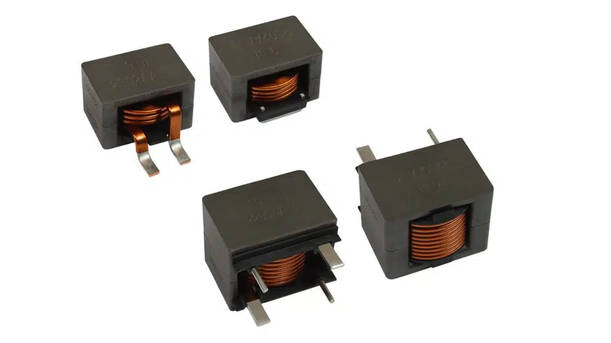
Vishay has introduced the first four members of a new IHDV high voltage power inductor family designed for next‑generation automotive, energy, and industrial power stages.
The Vishay power inductor parts combine 1.5 kV isolation capability, high operating temperature, and soft saturation behaviour in relatively compact 0808 and 1008 case sizes, which makes them interesting building blocks for on‑board chargers, PFC stages, and high voltage DC battery filters.
Key features and benefits
- High isolation rating for HV buses
The IHDV series is specified for 1.5 kV isolation voltage thanks to a PET plastic coilform insulator, extending the voltage capability beyond the roughly 350 V typical of many general‑purpose power inductors. This makes the family suitable for the 400 V and 800 V class DC buses commonly found in EV and industrial energy storage systems. - Compact geometries for dense layouts
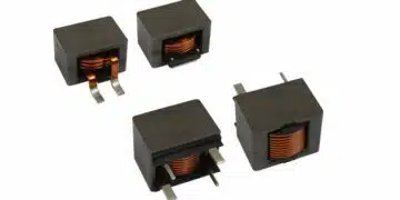
The initial devices are offered in two case sizes: 0808 with dimensions of 20 mm × 14 mm × 14 mm and 1008 with 25 mm × 20 mm × 23 mm. The 0808 SMD versions provide a footprint at roughly one‑third the volume of the larger 1008 devices, which is valuable when fitting magnetics into crowded OBC or DC/DC converter layouts. - Soft saturation for controlled ripple
A powdered iron alloy core gives the inductors soft saturation characteristics, so inductance remains relatively stable over current, improving control of ripple in PFC chokes or high voltage DC filters. According to the specification, the inductors can withstand transient inrush currents up to approximately five times their heat rating current, providing headroom for start‑up and fault events. - High impedance for EMI suppression
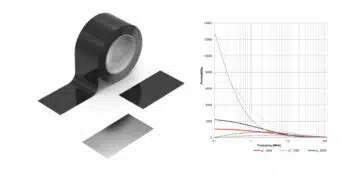
For high frequency filtering, the IHDV inductors provide significantly higher impedance than similarly sized iron composite parts. The 0808 devices reach around 1 kΩ at a peak frequency of 80 MHz, while the 1008 size can reach approximately 2.8 kΩ at 25 MHz, which supports differential‑mode noise attenuation in converters with fast switching edges. - Automotive‑grade options and mechanical robustness
Two of the four initial parts (IHDV‑0808AC‑3A and IHDV‑1008BB‑3A) are Automotive Grade and AEC‑Q200 qualified, while their commercial counterparts serve non‑automotive applications. All devices are RoHS‑compliant, halogen‑free, rated for continuous operation up to 180 °C, and include additional support pins to improve resistance to shock and vibration.
Typical applications
The new IHDV inductors are clearly oriented towards high voltage and high power environments where isolation and EMI behaviour are critical design constraints.
- On‑board chargers in EVs and plug‑in hybrids, especially for 400 V and 800 V battery systems.
- High voltage DC battery filtering stages, including traction battery interfaces and auxiliary HV buses.
- Power factor correction (PFC) inductors in AC/DC front ends of chargers and industrial power supplies.
- Battery‑charging circuits in energy storage systems and industrial chargers.
- General high voltage DC filtering in inverters, rectifiers, and DC/DC converters where 1.5 kV isolation margin is required.
In many of these cases, the combination of isolation, impedance at RF, and high temperature capability allows the same component to contribute both to energy storage and to EMI filtering, which can simplify the overall magnetics strategy of the design.
Technical highlights
Four part numbers are released initially, covering automotive and commercial variants in two mechanical formats.
Product family and mechanical options
- IHDV‑0808AC‑3A: Automotive Grade, 0808 SMD package.
- IHDV‑0808AC‑30: Commercial grade, 0808 SMD package.
- IHDV‑1008BB‑3A: Automotive Grade, 1008 through‑hole package with support pins.
- IHDV‑1008BB‑30: Commercial grade, 1008 through‑hole package with support pins.
The 0808 versions are surface‑mount and target space‑constrained boards, while the 1008 versions use through‑hole terminations and additional support pins to maximise mechanical strength in harsh environments, for example when inductors are mounted on boards subject to continuous vibration.
Core and insulation system
- PET plastic coilform insulator providing 1.5 kV isolation capability.
- Powdered iron alloy core material enabling soft saturation behaviour.
- High operating temperature capability, with continuous operation specified up to 180 °C according to the manufacturer’s data.
From a design point of view, the use of a plastic coilform combined with a suitable creepage and clearance strategy allows the component to meet increased isolation demands in modern high voltage systems without significantly upsizing the package.
Example specification data
The table below summarises representative values for the family according to the manufacturer.
| Parameter | IHDV‑0808AC‑3A | IHDV‑0808AC‑30 | IHDV‑1008BB‑3A | IHDV‑1008BB‑30 |
|---|---|---|---|---|
| Package style | 0808 SMD | 0808 SMD | 1008 THT | 1008 THT |
| Dimensions (mm) | 20 × 14 × 14 | 20 × 14 × 14 | 25 × 20 × 23 | 25 × 20 × 23 |
| Inductance (µH, example value) | 1.9 | 10 | according to manufacturer datasheet | according to manufacturer datasheet |
| Typical DCR (mΩ) | 1.3 | 2.7 | according to manufacturer datasheet | according to manufacturer datasheet |
| Maximum DCR (mΩ) | 1.5 | 2.9 | according to manufacturer datasheet | according to manufacturer datasheet |
| Typical heat rating current (A) | 30.0 | 30.0 | 30.0 (typ., similar class) | 30.0 (typ., similar class) |
| Typical saturation current (A) | 110 | 68 | according to manufacturer datasheet | according to manufacturer datasheet |
| Typical self‑resonant frequency (MHz) | 83 | 22 | according to manufacturer datasheet | according to manufacturer datasheet |
| AEC‑Q200 qualification | Yes | No | Yes | No |
Heat rating current is defined as the DC current which causes an approximate 40 °C temperature rise of the component, while saturation current is defined as the DC current at which the initial inductance drops by about 30%, so both parameters need to be interpreted with appropriate design margin.
Design‑in notes for engineers
Selecting between 0808 and 1008
- The 0808 SMD devices are a good fit where PCB real estate is limited and assembly is optimised for reflow soldering; their footprint is about one‑third of the 1008 package. The 1008 devices, with through‑hole pins and extra support pins, will be more attractive in high vibration environments, such as under‑hood ECUs, board‑to‑chassis mounts, or industrial drives, where mechanical robustness overrides the desire for purely SMD assembly.
Current ratings and derating strategy
- Use the heat rating current as an indication of thermal capability under steady‑state DC conditions, but include margin for ambient temperature, airflow, and neighbouring hot components, especially as the device can operate up to 180 °C.
- Treat the saturation current as the upper bound for maintaining inductance within about 70% of its initial value; in many topologies, especially those sensitive to ripple magnitude, it is advisable to operate significantly below this value.
- The ability to withstand inrush currents up to around five times the heat rating current is useful for start‑up and fault events, but should not be interpreted as a continuous operating point.
Isolation, creepage and clearance
- The 1.5 kV isolation rating is enabled by the PET coilform, but overall safety compliance still depends on PCB layout, pollution degree, and relevant standards such as IEC 60664‑1 and automotive OEM specifications. When designing for 800 V battery systems or grid‑connected chargers, designers should verify creepage and clearance distances on the PCB and between adjacent components to maintain the intended insulation coordination.
EMI and impedance behaviour
- The relatively high impedance at RF makes these inductors suitable not only as energy‑storage elements but also as part of differential‑mode EMI filters in converters using fast wide‑bandgap devices. Designers should review the impedance versus frequency and self‑resonant frequency curves in the datasheet to ensure that the chosen inductance value supports the desired attenuation in the relevant frequency bands.
Thermal and mechanical integration
- Operation up to 180 °C simplifies thermal design in hot environments, but PCB materials, solder joints, and nearby components must also withstand these temperatures. The additional support pins improve vibration performance; layout engineers should reserve appropriate pads or holes for these supports and consider the mechanical load path into the PCB.
Source
This article is based on information provided in the official Vishay Intertechnology press release on the IHDV 1.5 kV high voltage power inductor family and associated product pages on the manufacturer website.