


Würth Elektronik has reworked its SMT spacer portfolio to use lead‑free alloys and added new assembly options targeted at high‑volume SMT production.
The changes give design and manufacturing teams a clearer RoHS roadmap and more flexibility in how they place and inspect mechanical spacers on densely populated PCBs.
Key features and benefits
Würth Elektronik’s SMT spacers are now specified with a lead content below 0.1 percent in line with the RoHS Directive thresholds. This means the affected product families are considered lead‑free under current European environmental regulations and are designed to support long‑term compliance as existing exemptions expire.
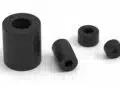
The restructuring covers several SMT spacer families:
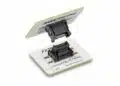
- WA‑SMSI series: SMT spacers with internal thread for screw mounting into the spacer.
- WA‑SMST series: push‑through system where the spacer passes through the PCB for additional mechanical security.
- WA‑SMSR series: spacers for the underside of the PCB, enabling offset or multi‑level boards from below.
- WA‑SMSSR series: spacers with a matched expansion rivet that snaps into place as a fixed mechanical anchor.
From a practical standpoint, moving to lead‑free alloys:
- Reduces redesign risk when RoHS exemptions end, because layouts built around these spacers will remain compatible.
- Avoids requalification loops and compliance audits triggered by mechanical parts that still contain lead.
- Supports use with standard lead‑free solder pastes and profiles, simplifying SMT process integration.
To maintain reliability, the lead‑free variants have undergone extended testing and qualification according to Würth Elektronik’s internal quality standards. Designers can therefore treat the new versions as drop‑in successors within the same mechanical and functional envelope, with the detailed limits and tests taken from the manufacturer datasheets.
Typical applications
SMT spacers are mechanical components, but they are increasingly critical in reliable PCB system design, especially in compact or mechanically stressed assemblies. Typical uses for these Würth Elektronik spacers include:
- Multi‑level PCB stacks where daughterboards are mounted above a baseboard to save footprint in enclosures.
- Mounting and stabilizing sensors, LEDs, and small display modules at defined heights relative to the main PCB or front panel.
- Fixing PCBs to metallic or plastic housings while controlling creepage distances and mechanical clearance.
- Providing local support points under large or heavy PCBs to reduce bending, vibration stress, and solder joint fatigue.
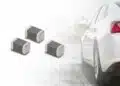
In many power electronics, industrial controllers, and automotive ECUs, SMT spacers are used alongside conventional fasteners to support large boards exposed to vibration or thermal cycling. The availability of lead‑free, RoHS‑compliant variants simplifies sourcing and documentation for these regulated markets.
Technical highlights
Lead‑free alloy and RoHS compliance
The new SMT spacers are manufactured with a lead content below the 0.1 percent threshold defined in the RoHS Directive. This aligns the product with the requirements of 2011/65/EU and its amendment 2015/863/EU as referenced by Würth Elektronik.
For engineers, the relevant practical points are:
- The spacers can be processed with standard lead‑free solder pastes.
- The material composition has been qualified so that switching to the lead‑free variant does not introduce unexpected solderability or wetting issues when used within the recommended process window.
- Environmental compliance documentation relates directly to the RoHS legislation cited, which simplifies technical file preparation.
Tin surface finish and reflow robustness
The spacers use a tin surface finish optimized for lead‑free reflow processes. Würth Elektronik highlights that the parts are designed to withstand multiple reflow cycles without visible or functional surface degradation, such as discoloration, blistering, or cracking.
In practice, this allows:
- Use on assemblies that see more than one reflow step, for example double‑sided population or subsequent rework within the specified profile.
- Stable mechanical joints when combined with appropriate pad geometries and solder paste volumes.
- High holding forces and torque resistance, which are critical when spacers are used as screw anchors or structural supports.
The exact tin layer thickness and test methods are defined in the respective product datasheets, and designers should validate mechanical safety margins for highly loaded points against those specifications.
Design‑in notes for engineers
Choosing the right spacer family
When designing in these SMT spacers, the choice of family should reflect both mechanical and assembly constraints:
- Use WA‑SMSI (internal thread) where a threaded metal insert on the PCB is required, for example to fasten covers, shields, or subassemblies from above.
- Use WA‑SMST (push‑through) where higher pull‑out strength is required by passing the spacer through the PCB, or where a defined through‑hole geometry is already present.
- Use WA‑SMSR (underside spacing) to build multi‑level stacks without additional hardware on the top side, or to create clearance under the PCB for airflow and insulation.
- Use WA‑SMSSR (with expansion rivet) when a fixed snap‑in solution is needed that locks mechanically without additional screws.
In all cases, ensure that pad or hole dimensions follow the manufacturer’s recommended land pattern, since this directly affects solder fillet formation and holding force.
SMT assembly options: R, RR, and RX
A second key change is the expanded range of SMT assembly aids, which directly impacts PCB population and inspection strategies.
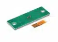
Previously, the spacers were only offered with an assembly aid designated “R”: a polyimide film with a small tab used to support pick‑and‑place handling and later removal. Würth Elektronik now adds two new options:
- “RR” option: a circular polyimide film without the tab. This variant addresses situations where the original tab might obstruct optical inspection or automated optical inspection (AOI) of small neighboring components. Removing the tab gives a cleaner AOI field of view at the cost of slightly more complex manual handling when removing the film.
- “RX” option: a version supplied with no film at all, intended specifically for mass production. In this case, specialized nozzles on the pick‑and‑place machine grip the spacer directly, eliminating both the film material and the manual removal step.
From a process engineering perspective:
- “R” remains useful for low‑ to medium‑volume production or where standard nozzles are used and manual film removal is acceptable.
- “RR” is a compromise for automated lines that rely heavily on AOI; it reduces遮 obstruction without requiring new nozzle designs.
- “RX” is best suited to high‑volume lines willing to implement dedicated nozzles, rewarding that investment with reduced consumables and cycle times.
The choice should be coordinated between hardware design, process engineering, and quality teams, since it affects both panel design (clearance around the spacer) and the AOI strategy.
Mechanical and reliability considerations
When using SMT spacers as structural elements, some basic design‑in practices are recommended:
- Place spacers near heavy components, connectors, or mounting points where mechanical stress is highest.
- Distribute spacers so that PCB deflection under expected loads (vibration, handling, torque on screws) stays within acceptable limits.
- Where spacers are used as screw anchors, confirm that the specified torque limits in the datasheet are not exceeded in assembly or service.
- Ensure that solder joints at the spacer interface are not used as the only mechanical element in high‑shock environments; combine with suitable mechanical design, such as multiple spacers or additional supports.
Given that the lead‑free spacers are specified to tolerate multiple reflow cycles, they can be used even in assemblies that undergo rework, provided that the maximum number of cycles and profile limits from the manufacturer are respected.
Source
This article summarizes and interprets technical information published by Würth Elektronik in its official press release on lead‑free SMT spacers and new SMT assembly options, with detailed parameters and limits to be taken from the corresponding manufacturer datasheets.
References
- Würth Elektronik press release: Lead-Free and with More Options for SMT Assembly
- Würth Elektronik WA-SMSI SMT spacer with internal thread – product family overview
- Würth Elektronik WA-SMST SMT spacer push-through system – product family overview
- Würth Elektronik WA-SMSR SMT spacer underside version – product family overview
- Würth Elektronik WA-SMSSR SMT spacer with fixed snap rivet – product family overview