








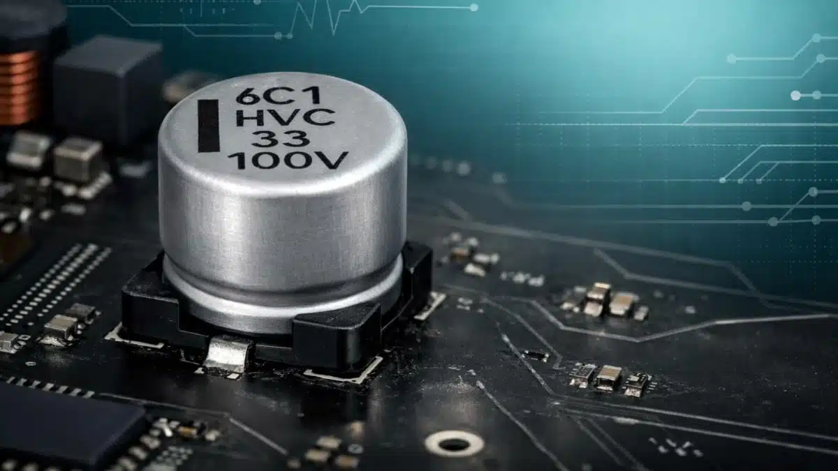
VINA Enesol, part of VINATech group, has introduced a 100 V hybrid polymer aluminium capacitor targeting next‑generation 48–72 V DC architectures in automotive, industrial and telecom equipment.
The VINATech Enesol hybrid polymer aluminium capacitor combines high voltage rating, low ESR and high ripple current capability in a compact SMD package, addressing a long‑standing gap above the 80 V limit of most hybrid polymer capacitors.
Key features and benefits
- True 100 V rating for 48–72 V buses
The capacitor is rated at 100 V with a surge test level of 125 V, providing meaningful voltage margin for 48 V, 60 V and 72 V systems that must withstand transients, surges and load‑dump conditions. - 33 µF capacitance in 10 × 10.5 mm case
The initial product 100HVK33ME10 offers 33 µF high capacitance in a 10 × 10.5 mm SMD footprint, supporting compact input and output filtering in dense power designs where board area is at a premium. - Hybrid polymer aluminium technology
The component uses a hybrid polymer aluminium construction, combining a conductive polymer with a liquid electrolyte to achieve low ESR, stable performance at high frequency and improved lifetime compared with conventional wet electrolytics. - Low ESR and high ripple capability
ESR is specified at 35 mΩ maximum at 100 kHz with ripple current capability up to 1300 mA, enabling efficient handling of high‑frequency ripple in switching converters and DC link stages. - High‑temperature endurance at 125 °C
Endurance for the 100HVK33ME10 is specified as 4000 hours at 125 °C, which corresponds to extended life at lower operating temperatures and enables use in harsh automotive and industrial environments close to heat sources. - Standard and anti‑vibration SMD options
The 100 V / 33 µF device is available in both standard SMD and anti‑vibration SMD versions, making it suitable for applications exposed to mechanical shock and vibration, such as automotive ECUs, industrial machinery and mobile robotics.
Initial product specification
| Parameter | Specification |
| Rated voltage | 100 V |
| Surge voltage | 125 V (charge/discharge testing) |
| Capacitance | 33 µF |
| Part number | 100HVK33ME10 |
| Case size | 10 × 10.5 mm (SMD) |
| Endurance | 4000 h at 125 °C |
| ESR | ≤ 35 mΩ at 100 kHz |
| Ripple current | Up to 1300 mA |
| Technology | Hybrid polymer aluminium capacitor |
| Series options | Standard SMD and anti‑vibration SMD |
Typical applications
Hybrid polymer capacitors with a true 100 V rating are particularly attractive wherever designers currently operate near the limits of 63–80 V components or resort to bulky film capacitors.
- 48 V automotive subsystems
Typical 48 V rails in mild‑hybrid systems, belt‑starter generators, electric turbos, active suspension or electric steering benefit from additional voltage margin against load‑dump and transient events. - 60–72 V mobile and industrial equipment
Battery‑powered AGVs, AMRs, smaller e‑mobility platforms and professional tools operating from 60–72 V packs can use the 100HVK33ME10 as a DC link or input filter capacitor where compact size and high ripple capability are required. - Industrial power supplies and DC/DC converters
Front‑end DC links, intermediate bus filters and high‑side stages in industrial SMPS, servo drives and machine controllers can take advantage of low ESR and high‑temperature operation for improved reliability and efficiency. - Telecom and networking infrastructure
48 V rectifiers, power shelves and remote radio units deployed in outdoor or base station environments with elevated temperatures and wide load dynamics can use the hybrid polymer device for output smoothing and intermediate bus filtering. - Renewable energy systems
DC link and filter stages in compact solar inverters, DC optimisers or energy storage converters benefit from the combination of high voltage rating, compact footprint and robust high‑temperature performance.
Technical highlights
The development of the 100 V EneCap hybrid polymer capacitor focused on three core technology areas: conductive polymer formulation, separator structure and electrolyte composition, aiming to maximise voltage withstand, suppress gas generation and keep ESR low across the operating range.
From the published data, several aspects are particularly relevant for design‑in:
- Rated voltage and surge margin
The 100HVK33ME10 is rated at 100 V and subjected in testing to a 125 V surge voltage in repeated charge/discharge cycling, indicating substantial headroom above typical nominal bus voltages in 48–72 V systems. - Capacitance and form factor
A 33 µF capacitance in a 10 × 10.5 mm case is tuned for compact DC link and filtering rather than bulk energy storage, making it suitable as a high‑performance replacement for legacy aluminium electrolytics in similar footprints. - ESR and ripple behaviour
ESR is specified at 35 mΩ or less at 100 kHz, while ripple current capability reaches up to 1300 mA, supporting high‑frequency current handling in switching applications with limited temperature rise. - Endurance and temperature range
The endurance rating of 4000 hours at 125 °C, combined with successful 1000 hour HALT evaluations at 150 °C and 100 V, suggests robust operation under elevated thermal stress when appropriate derating is applied at the application level.
Harsh environment robustness – HALT test results
HALT at 150 °C and 100 V
The second evaluation used a HALT‑style profile: Continuous application of rated voltage 100 V for 1000 hours at 150 °C with no series resistor.
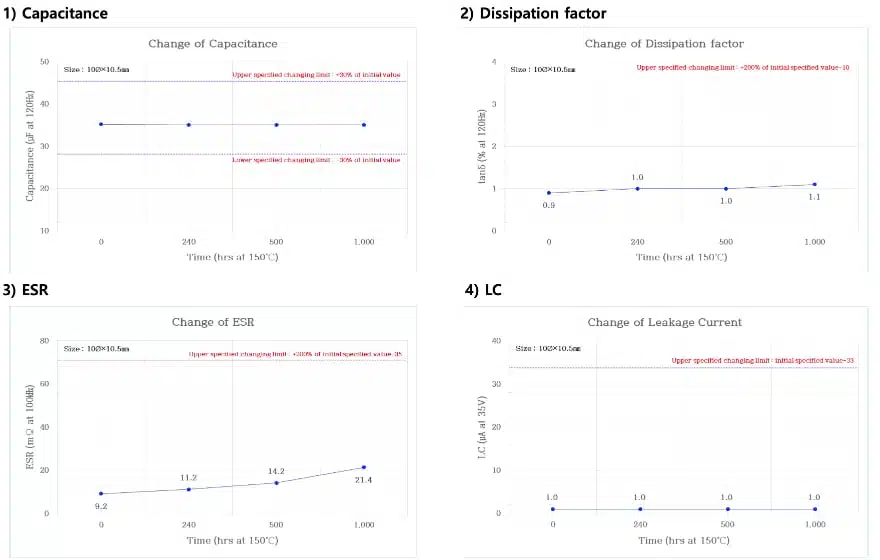
Over the 0–1000 hour HALT duration, results show:
- Capacitance remained in the mid‑30 µF range (approximately 35.3 to 34.9 µF) and within the specified change limit of ±30% at 150 °C.
- Dissipation factor increased slightly over time but remained near 1.0–1.3%, still significantly below the 10% maximum.
- ESR rose from around 9.2 mΩ at the start to 21.4–25.8 mΩ after 1000 hours, yet stayed comfortably under the 35 mΩ limit.
- Leakage current, measured at 35 V in the presented chart, remained at about 1 µA, equal to the initial value and far below the upper specification line.
These HALT results support the manufacturer’s claim of stable electrical characteristics under extreme combined temperature and voltage conditions, and they provide useful data points for lifetime and derating assessments in high‑temperature installations.
Complete Test Datapackage is available from the manufacturer upon request.
Comparison with existing 100 V hybrid capacitors
Benchmark comparison between the EneCap 100 V / 33 µF capacitor and existing 100 V hybrid aluminium capacitor vendor suppliers.
100 V hybrid capacitor comparison
| Parameter | Supplier 2 15 µF | Supplier 3 18 µF | EneCap 33 µF |
| Capacitance (µF) | 15 | 18 | 33 |
| Size [Ø × L] (mm) | 10 × 10.5 | 10 × 12.5 | 10 × 10.5 |
| Endurance (°C / h) | 125 / 4000 | 125 / 4000 | 105 / 10000, 125 / 4000, 150 / 1000 |
| ESR / ripple (mΩ / mA) | 45 / 1120 | 40 / 1220 | 35 / 1600, 35 / 1300, 35 / 1100 |
In practice, this means that for the same 10 × 10.5 mm footprint, the EneCap device roughly doubles capacitance compared with a 15 µF supplier 2 capacitor while also providing lower ESR and higher ripple current capability, plus endurance options up to 150 °C. This is particularly relevant where designers want to increase energy storage or reduce the number of parallel capacitors without increasing PCB area.
Roadmap: higher‑capacitance 100 V hybrids
Beyond the initial 33 µF device, VINA Enesol outlines a development plan for additional 100 V‑grade hybrid capacitors in larger case sizes.
Planned 100 V EneCap roadmap devices:
| Capacitance (µF) | Size [Ø × L] (mm) | Endurance (°C / h) | ESR (mΩ) | Ripple (mA) | Target availability |
| 39 | 10 × 12.5 | 150 / 1000 | 30 | 1200 | ~Jun. 2026 |
| 56 | 10 × 16.0 | 150 / 1000 | 20 | 1500 | ~Dec. 2026 |
| 100 | 10 × 23.0 | 150 / 1000 | 15 | 2000 | ~Dec. 2027 |
For power designers, this roadmap suggests that a consistent 10 mm diameter platform will soon span from 33 µF up to 100 µF at 100 V, with progressively lower ESR and higher ripple capability, making it easier to scale designs without changing pad width or clearance around the capacitor body.
Design‑in notes for engineers
For design engineers considering a transition to the 100 V EneCap hybrid polymer capacitor, the following points can help streamline evaluation and qualification.
- Voltage margin strategy
- Use the 100 V rating and demonstrated 125 V surge cycling as a basis for voltage margin in 48–72 V buses, while still verifying that worst‑case operating conditions stay within the manufacturer’s specified surge and transient limits.
- For systems that may briefly exceed nominal bus voltage (for example during load‑dump), consider additional circuit‑level protection if surge levels are expected to go beyond the tested range.
- Thermal management and lifetime
- Combine the 4000 hour endurance at 125 °C with the 150 °C HALT data to estimate lifetime at the actual operating temperature of the capacitor; most data sheets provide guidance or models for such extrapolation.
- Pay attention to local PCB heating from power semiconductors and shunts, and, where necessary, use copper pours or airflow to keep capacitor case temperature within target limits.
- Ripple current and ESR considerations
- Use the specified ESR and ripple current capability to calculate internal power dissipation at the converter switching frequency and duty cycle, then verify that the resulting temperature rise is acceptable against the endurance requirement.
- In some designs, the low ESR may allow reduction of the number of parallel capacitors compared with legacy aluminium electrolytics, but always re‑check loop stability and transient response when changing total capacitance and ESR.
- Frequency behaviour and EMC
- Hybrid polymer capacitors typically maintain low ESR up to higher frequencies than classical wet electrolytics, which can improve attenuation of high‑frequency ripple and reduce EMI emissions.
- For stringent EMC requirements, combine the 100HVK33ME10 with high‑frequency MLCC decoupling or dedicated EMI filters to cover both the low‑frequency energy storage and high‑frequency noise suppression ranges.
- Mechanical robustness and mounting
- For applications with significant vibration or shock, such as automotive engine compartment ECUs or industrial motion systems, the anti‑vibration SMD version shown in the test report should be preferred.
- Follow the recommended land pattern and soldering profile from the data sheet to minimise mechanical stress during assembly and thermal cycling, especially given the high temperature operating capability.
- Comparison to alternative technologies
- Compared with film capacitors of similar voltage rating, the EneCap hybrid polymer devices achieve much higher capacitance density and significantly lower ESR in a smaller footprint, which is beneficial in space‑constrained designs.
- Compared with stacking lower‑voltage polymer capacitors to achieve higher voltage margin, a true 100 V rated part simplifies layout, reduces component count and may ease qualification in high‑reliability sectors such as automotive or industrial.
For critical safety or long‑lifetime applications, engineers should always cross‑check operating conditions against the latest manufacturer data sheet, including any derating curves, surge voltage limits, ripple current versus temperature characteristics and failure mode information, rather than relying solely on headline figures in press or test summaries.
Source
The information in this article is based on an official VINA Enesol press release on its 100 V hybrid polymer aluminium capacitor platform and an April 2026 harsh test report for the 100HVK33ME10 device, supplemented by data from the company’s catalogue and product pages.
References
- VINA Enesol – Polymer hybrid capacitors (EneCap)
- VINA Enesol – Company and product catalogue
- VINA Enesol Harsh test report of Al Polymer Hybrid capacitor, Product: 100HVK33ME10 (100V/33µF – 10Ø × 10.5mm), – June 2026, available upon request by manufacturer