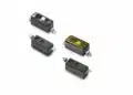
ROHM has introduced the SDR01 series of high anti-surge thick-film chip resistors in the 1005 metric (0402 imperial) package.
The new series combines a 0.33 W rated power with anti-surge performance in a footprint normally selected where PCB area is tightly constrained.
According to ROHM, the SDR01 series uses optimised resistive-element and electrode designs to support higher power handling and improved anti-surge characteristics versus the company’s ESR series. The products target compact power-supply, control, and interface circuits in automotive, industrial, consumer, and AI-server equipment.
Key features and benefits
- 0.33 W rated power in 0402 size: ROHM specifies 0.33 W for the 1005 metric package, enabling a higher-power option where a conventional larger chip resistor might otherwise be required.
- High anti-surge thick-film construction: The SDR01 is a specialised thick-film resistor family for circuits exposed to defined surge, inrush, discharge, or transient stress. This does not mean that every surge waveform is permissible; selection still depends on the current datasheet pulse-load data for the exact resistance value.
- Rated terminal temperature of 125°C: ROHM states that full rated power is guaranteed up to a terminal temperature of 125°C. Terminal temperature is more relevant than ambient temperature alone because copper area, pad design, airflow, adjacent heat sources, and board stack-up determine the resistor’s actual thermal condition.
- Automotive qualification: The SDR01MZPJ product family is listed as AEC-Q200 qualified. AEC-Q200 is a passive-component stress-test qualification framework; it does not by itself complete vehicle-level, module-level, or mission-profile validation.
- Broad resistance range: The published SDR01 family range is 1 Ω to 10 MΩ. Available tolerance, TCR, voltage limits, pulse capability, and derating behaviour must be verified for the specific ordering code.
Technical highlights
| Parameter | Published information |
|---|---|
| Series | ROHM SDR01 |
| Resistor technology | High anti-surge thick-film chip resistor |
| Package size | 1005 metric / 0402 imperial |
| Rated power | 0.33 W |
| Resistance range | 1 Ω to 10 MΩ |
| Operating temperature | -55°C to +155°C |
| Maximum rated terminal temperature | 125°C |
| Qualification | AEC-Q200 qualified |
| Example tolerance | J (±5%) for SDR01MZPJ |
| TCR for F-tolerance parts | ±100 ppm/°C for 10 Ω to 2.2 MΩ |
ROHM states that the ±100 ppm/°C TCR applies to F-class, ±1% tolerance products from 10 Ω to 2.2 MΩ. This parameter should not be transferred automatically to other resistance ranges or tolerance classes: the SDR01MZPJ product page, for example, lists different TCR options for its ±5% version.
Application fit
ROHM identifies power-supply and control circuits in automotive, industrial, and consumer equipment as target uses. The announcement also identifies AI-server electronics, where board density and local thermal loading can make compact high-power resistor options relevant.
Possible circuit positions include:
- Input and auxiliary-power networks with restricted PCB area
- Control and bias circuits located near thermally active power devices
- Interface circuits requiring defined resistance to surge and ESD-related stress
- Damping, current-limiting, discharge, or protection functions, provided that the exact pulse waveform and duty remain within the manufacturer’s limits
- Compact automotive electronic control modules where AEC-Q200 qualification is part of the component requirement
A 0.33 W steady-state rating does not demonstrate suitability for all pulse or surge events. Engineers should use the thick-film chip resistor design guide to distinguish continuous dissipation, limiting voltage, peak pulse power, pulse energy, repetition rate, and allowable post-test resistance change.
Design-in notes for engineers
- Check the correct derating condition. ROHM’s 0.33 W claim is tied to a rated terminal temperature of 125°C. Confirm the applicable derating curve and assess the final PCB’s copper spreading, local heating, enclosure temperature, and airflow.
- Validate pulse stress separately from average power. Determine the actual surge, inrush, capacitor-discharge, switching, or fault waveform; then verify peak voltage, peak current, duration, repetition count, source impedance, and permitted resistance shift against the current manufacturer datasheet.
- Do not select solely by package size. The 0402 outline does not define maximum operating voltage, limiting element voltage, pulse capability, or thermal performance. These limits can depend on resistance value, trimming geometry, mounting arrangement, and test conditions.
- Confirm the TCR and tolerance combination. The announced ±100 ppm/°C specification is limited to specified F-tolerance products and resistance values. Use the selected part number’s data when circuit accuracy is temperature-sensitive; see also What Is High-Precision Resistor Temperature Coefficient of Resistance.
- Treat AEC-Q200 correctly. Confirm the exact qualified ordering code, customer-specific documentation, traceability, change-control requirements, environmental exposure, and system-level validation plan. For wider context, see MIL Specifications and Automotive AEC-Q200 Qualification Explained.
- Verify assembly conditions. Use ROHM’s recommended land pattern and soldering conditions for the 0402 package. Small chip resistors are sensitive to pad asymmetry, board flexure, excessive solder volume, and thermal gradients.
- Validate on the populated board. Measure terminal and local board temperatures at worst-case voltage, load, ambient temperature, and neighbouring-component heat. Confirm resistance drift after representative electrical and thermal stress before production release.
Further reading
- Thick-Film Chip Resistors: Construction, Properties, Selection and Design Guide
- Resistor Pulse Load, Power and Voltage Derating Design Guide
- What Is a Resistor? Basic Principles, Functions and Parameters
- MIL Specifications and Automotive AEC-Q200 Qualification Explained
Source
This article is based on ROHM’s manufacturer press release and current official SDR01 product documentation. Engineers should consult the current manufacturer datasheet, series documentation, pulse-load curves, derating information, and assembly guidance for final component qualification and design release.