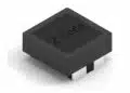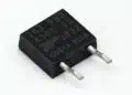



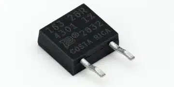


Bourns has introduced the MSF series of four-terminal current-sense shunt resistors for power conversion, battery management and industrial equipment.
The current-sense shunt resistors MSF-2 and MSF-2L models combine a 0.5 mΩ to 5 mΩ resistance range with a 5 W power rating and a maximum current rating of 100 A. Their Kelvin terminal arrangement separates voltage sensing from the current-carrying connections to reduce measurement errors caused by lead resistance.
Key features and benefits
- Kelvin sensing: Four terminals separate the current path from the voltage-sense connections.
- Resistance range of 0.5 mΩ to 5 mΩ, with standard tolerance options spanning ±0.5% to ±10%.
- Power rating of 5 W and maximum current rating of 100 A.
- Temperature coefficient of resistance of ±100 ppm/°C over 0 °C to +85 °C.
- Operating temperature range of −55 °C to +275 °C.
- Manganin resistance element welded to oxygen-free high-conductivity copper terminals.
- Flame-retardant, high-temperature silicone coating.
- Radial, self-supporting construction for PCB mounting.
Technical highlights
The MSF series comprises the MSF-2 and MSF-2L models. Both use a welded metal resistance element and four-terminal measurement architecture.
| Parameter | MSF series |
|---|---|
| Models | MSF-2, MSF-2L |
| Resistance range | 0.5 mΩ to 5 mΩ |
| Power rating | 5 W |
| Maximum current | 100 A |
| Standard tolerance range | ±0.5% to ±10% |
| TCR | ±100 ppm/°C |
| TCR temperature interval | 0 °C to +85 °C |
| Operating temperature | −55 °C to +275 °C |
| Mounting | Radial PCB |
| Compliance | RoHS |
Measurement accuracy and temperature
The Kelvin arrangement addresses the contribution of lead resistance to the sensed voltage. Separate voltage-sense connections allow the measurement circuit to sense across the resistance element rather than include the voltage drop along the current-carrying leads.
Initial resistance tolerance and temperature coefficient remain separate selection criteria. Tolerance governs the starting resistance error, while TCR governs resistance change with temperature. The ±100 ppm/°C TCR applies over 0 °C to +85 °C; that interval is distinct from the wider operating temperature range.
Resistance, current and thermal loading
Resistance selection affects both the available sense voltage and the heat generated in the current path. The 0.5 mΩ to 5 mΩ range provides a choice between a smaller voltage drop and a larger measurement signal.
The 5 W power rating and 100 A maximum current rating are separate limits that must be assessed together. The maximum current figure is not a continuous-current allowance for every resistance value or thermal condition. Likewise, the +275 °C operating-temperature endpoint is not a full-power operating condition.
Typical applications
Target applications include:
- Battery management systems and energy storage systems.
- Power supplies and power conversion equipment.
- Industrial motor controls.
- Current monitoring circuits.
- Welding equipment.
- Industrial automation and control systems.
The four-terminal architecture supports current measurement in these systems by separating the sensing connections from the load-current connections. The resistance range, tolerance and TCR govern the resistor’s contribution to the measurement error budget, while current and power limits govern its electrical and thermal loading.
For battery management and energy storage, resistance selection balances sensing signal against dissipation in the monitored current path. Power conversion, motor control and welding equipment also require attention to the operating current waveform and the resulting thermal load.
Design-in notes for engineers
- Select resistance against the required sensing signal and allowable dissipation, rather than choosing from the maximum current rating alone.
- Route the voltage-sense connections separately from the load-current path to preserve the Kelvin measurement arrangement.
- Budget initial resistance tolerance and temperature-dependent resistance change separately.
- Assess resistor temperature under load together with PCB and surrounding-component temperatures.
- Match the PCB mounting arrangement to the selected MSF-2 or MSF-2L model.
- Validate the completed current-measurement circuit under its actual electrical and thermal operating conditions before production release.
Further reading
Source
This article is based on the Bourns product announcement and official product documentation. Engineers should refer to the current manufacturer datasheet for final design and qualification.
References
- Bourns Releases Four-Terminal Shunt Power Resistors — MSF Series, Bourns, October 30, 2026.