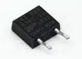

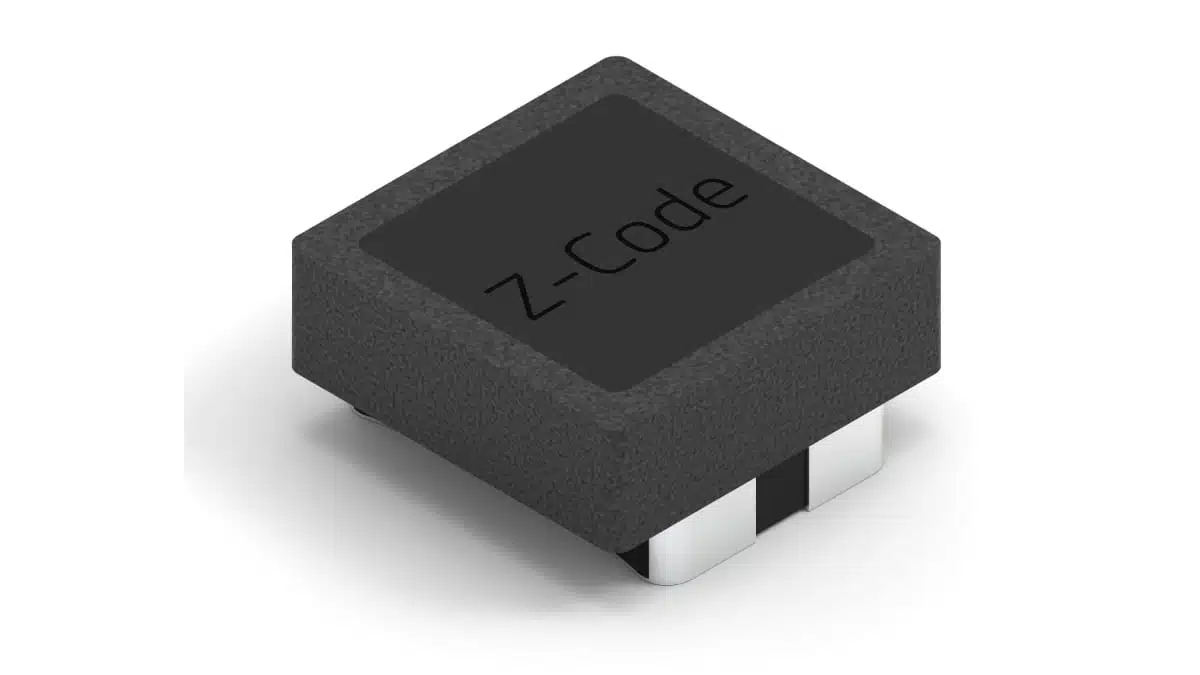
Würth Elektronik has introduced the WE-SLSP series of SMT common-mode chokes for signal and data lines, including applications that combine data transmission and power delivery.
The series combines a 100 V DC rating with a 5 × 5 mm nominal package and a maximum height of 2.5 mm, providing an EMI-filtering option where assembly height and current capacity both govern component selection. Seven variants cover typical common-mode impedances from 100 Ω to 1800 Ω at 100 MHz and rated currents from 1.3 A to 6 A.
Key features and benefits
- SMT construction in a 5050 package with four terminals and a maximum height of 2.5 mm.
- A common 100 V DC rated voltage across the series.
- Rated currents from 1.3 A to 6 A, defined at 20 °C ambient with a 40 K temperature rise.
- Maximum DC resistance from 15 mΩ to 73 mΩ at 25 °C, depending on the variant.
- AEC-Q200 Rev. E qualification.
- Ambient temperature range of −40 °C to +80 °C and component operating temperature range of −40 °C to +125 °C.
The common-mode choke uses coupled windings to suppress common-mode interference while passing the intended differential signal or load current. Opposing differential currents cancel their magnetic flux in the shared core. The windings provide functional insulation rather than a safety-isolation barrier.
Technical highlights
Impedance, current and resistance options
All variants share the same nominal package dimensions and rated voltage. Selection centres on the required impedance over the interference-frequency range, current capacity and winding resistance. The impedance figures below are typical values at 100 MHz; DC resistance values are maxima at 25 °C.
| Part number | Impedance at 100 MHz | Rated current | Maximum DC resistance |
|---|---|---|---|
| 744241101 | 100 Ω | 6 A | 15 mΩ |
| 744241251 | 250 Ω | 5 A | 20 mΩ |
| 744241501 | 530 Ω | 4 A | 30 mΩ |
| 744241701 | 1000 Ω | 3.5 A | 35 mΩ |
| 744241102 | 1000 Ω | 2 A | 45 mΩ |
| 744241142 | 1400 Ω | 1.5 A | 55 mΩ |
| 744241202 | 1800 Ω | 1.3 A | 73 mΩ |
The rated-current values use a 40 K temperature-rise criterion at 20 °C ambient. They are thermal ratings, not inductance-drop saturation ratings. Ambient temperature and self-heating must be assessed together because the component operating temperature includes both.
The two 1000 Ω variants illustrate why the 100 MHz value is insufficient for selection. The 744241701 has a typical impedance of 90 Ω at 10 MHz, a 3.5 A current rating and 35 mΩ maximum DC resistance. The 744241102 provides 130 Ω at 10 MHz, with a 2 A current rating and 45 mΩ maximum DC resistance. Their frequency response and electrical loading differ despite the matching 100 MHz impedance.
Frequency response matters more than a single impedance value
The 744241101 reaches a typical maximum impedance of 150 Ω at 500 MHz. The 744241202 reaches a typical maximum of 2050 Ω at 80 MHz, while its typical impedance at 100 MHz is 1800 Ω. These differences make the full common-mode impedance and differential-mode attenuation curves important when matching the choke to the interference spectrum and wanted signal.
Mechanical and thermal envelope
| Parameter | Value | Selection significance |
|---|---|---|
| Body length | 5.0 ±0.3 mm | Layout clearance |
| Body width | 5.0 ±0.3 mm | Layout clearance |
| Maximum height | 2.5 mm | Assembly clearance |
| Rated voltage | 100 V DC | Operating voltage |
| Ambient temperature | −40 °C to +80 °C | Local environment |
| Operating temperature | −40 °C to +125 °C | Includes self-heating |
| Moisture sensitivity | MSL 1 | Assembly handling |
The 100 V DC rating and the 300 V DC insulation-test voltage serve different purposes. The insulation-test value does not extend the operating-voltage rating or turn the functional insulation between windings into a safety barrier.
Typical applications
Target applications include USB-C ports in consumer electronics, PLC connections on 24 V to 48 V industrial bus systems, 48 V Power over Ethernet equipment in telecommunications, and microinverters for renewable-energy systems. The series also supports general signal and data-line filtering.
For industrial bus and PoE designs, the 100 V DC rating is relevant to voltage selection, while the 1.3 A to 6 A current range provides options for different line loads. The selected variant must also satisfy the required common-mode impedance and thermal conditions. The 2.5 mm maximum height is relevant to USB-C and other assemblies with restricted vertical clearance.
Application fit
The 744241101 combines the highest current rating in the family with the lowest maximum DC resistance: 6 A and 15 mΩ. At the other end of the range, the 744241202 provides 1800 Ω typical impedance at 100 MHz with a 1.3 A current rating and 73 mΩ maximum DC resistance. The choice therefore involves an impedance, current and resistance trade-off rather than selecting the largest impedance value by default.
For data paths, common-mode suppression and differential-signal transmission need to be assessed together. The common-mode and differential-mode impedance and attenuation characteristics provide the relevant frequency-dependent view; the nominal impedance at 100 MHz does not establish performance across the complete signal band.
Design-in notes for engineers
- Match the common-mode impedance curve to the frequencies requiring suppression, and assess differential-mode attenuation across the wanted signal band.
- Select the current rating using the local ambient temperature and the part-specific derating curve. Keep ambient temperature plus self-heating within the component operating-temperature limit.
- Check operating voltage against the 100 V DC rating. Treat the winding insulation as functional insulation, not a safety-isolation barrier.
- Use the recommended land pattern and terminal arrangement when preparing the PCB footprint. Include the body tolerances and maximum height in the mechanical layout.
- Match the production soldering process to the reflow profile. Evaluate cleaning agents and potting materials for compatibility with the winding insulation, marking and terminations.
Final selection should be validated under the actual operating conditions.
Further reading
Source
This article is based on the Würth Elektronik product announcement and official product documentation. Engineers should refer to the current manufacturer datasheet for final design and qualification.
References
- Filtering in the Tightest of Spaces, Würth Elektronik, 4 November 2026.
- WE-SLSP Common Mode Choke Line Slim Profile, Würth Elektronik.
- 744241101 — WE-SLSP Common Mode Data Line Choke, Würth Elektronik, 1 September 2026.
- 744241251 — WE-SLSP Common Mode Data Line Choke, Würth Elektronik, 1 September 2026.
- 744241501 — WE-SLSP Common Mode Data Line Choke, Würth Elektronik, 1 September 2026.
- 744241701 — WE-SLSP Common Mode Data Line Choke, Würth Elektronik, 1 September 2026.
- 744241102 — WE-SLSP Common Mode Data Line Choke, Würth Elektronik, 1 September 2026.
- 744241142 — WE-SLSP Common Mode Data Line Choke, Würth Elektronik, 1 September 2026.
- 744241202 — WE-SLSP Common Mode Data Line Choke, Würth Elektronik, 1 September 2026.