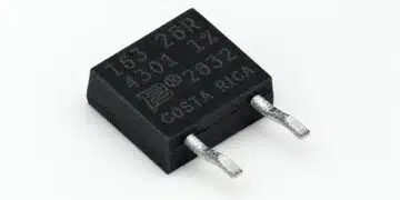



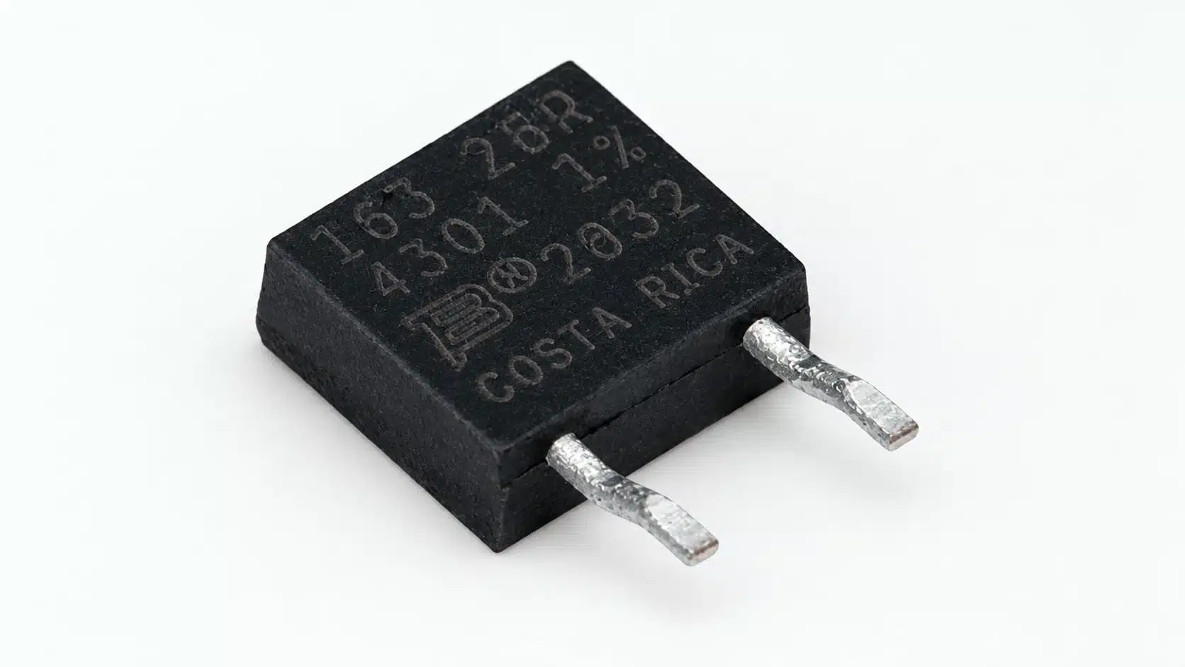
Bourns has introduced a reverse-pin configuration for its PWR163 series of DPAK-style surface-mount power resistors, together with reverse tape-and-reel and reverse tube packaging options.
The thick-film series covers 0.02 Ω to 130 kΩ and combines a 25 W rating at 25 °C case temperature with a maximum inductance of 0.1 µH for current-limiting, capacitor-discharge and high-frequency circuits.
Key features and benefits
- Reverse-pin configuration, with reverse tape-and-reel and reverse tube packaging options.
- Resistance range of 0.02 Ω to 130 kΩ, with ±1% and ±5% tolerance options depending on resistance value.
- Power rating of 25 W at a case temperature of 25 °C.
- Maximum inductance of 0.1 µH.
- Resistive element electrically isolated from the backplate.
- Operating temperature range of −55 °C to +155 °C.
- AEC-Q200 compliance and compatibility with lead-free solder reflow.
The configuration extension adds a mechanical and packaging choice within the PWR163 family. Pin arrangement and packaging orientation therefore belong in both the PCB assembly definition and the purchasing specification.
Technical highlights
Electrical and mechanical selection parameters
| Parameter | Value | Selection condition |
|---|---|---|
| Resistor technology | Thick film | Alumina substrate |
| Package style | DPAK-style SMD | Surface mounting |
| Package dimensions | 8.13 × 12.29 × 2.79 mm | Profile/package size |
| Resistance range | 0.02 Ω–130 kΩ | Value-dependent tolerance |
| Resistance tolerance | ±1%, ±5% | ±1% for most values |
| Temperature coefficient | ±100 ppm/°C | Resistance temperature dependence |
| Rated power | 25 W | 25 °C case temperature |
| Thermal resistance | 5.2 °C/W | Rthj |
| Maximum inductance | 0.1 µH | High-frequency selection |
| Operating voltage | , maximum 250 V | Power and resistance dependent |
| Dielectric strength | 2 kV AC | Insulation characteristic |
| Insulation resistance | 10 GΩ | Insulation characteristic |
| Operating temperature | −55 °C to +155 °C | Apply power derating |
The resistance values from 0.02 Ω through 0.075 Ω in the preferred-value range have ±5% tolerance. Selection of a ±1% component therefore depends on the chosen resistance, rather than the series-level tolerance options alone.
The operating-voltage limit is the lower of the power-derived value and the 250 V ceiling. The 2 kV AC dielectric-strength rating concerns insulation and does not increase the permissible voltage across the resistive element.
Case temperature governs usable power
The 25 W rating applies at 25 °C case temperature, not at 25 °C ambient temperature. The case-temperature derating curve reduces permissible dissipation as the case heats, reaching zero at 155 °C.
A separate board-mounted operating point is 2.8 W at 25 °C ambient on a double-sided FR4 board measuring 39 × 30 × 1.6 mm with 70 µm copper. This distinction makes the thermal path through the package, solder joints and PCB central to power selection. The nominal package wattage is not a substitute for assessing the installed assembly.
Construction and endurance
The PWR163 uses a thick-film resistor on an alumina substrate, an epoxy housing and tinned-copper pins. The backplate is electrically isolated from the resistor. Housing flammability conforms to UL 94 V-0, and moisture sensitivity is Level 1.
Load-life testing at rated power for 1,000 hours has a resistance-change limit of ±1.0%. Thermal-shock testing between −55 °C and +155 °C for five cycles has a resistance-change limit of ±0.5%. These are test acceptance limits, rather than a prediction of service life.
Typical applications
Current limiting and capacitor discharge
Current-limiting and capacitor-discharge circuits are supported applications. The 0.02 Ω to 130 kΩ resistance range provides the resistance choices, while permissible pulse energy, pulse duration and voltage govern whether a particular value fits the circuit.
Selection should use the PWR163 energy-versus-overload-duration curve alongside the continuous thermal limit. The overload voltage must not exceed 1.5 times the maximum operating voltage. Assessing resistor pulse loading and power derating is particularly important where discharge events repeat and the resistor starts each event above ambient temperature.
High-frequency circuits
Audio amplifiers and wireless base-station amplifiers are supported applications. The maximum inductance of 0.1 µH is a relevant selection parameter for these circuits, alongside resistance, dissipation and operating voltage.
Automotive and industrial power electronics
Target applications include automotive electronics, industrial power systems, precharge/discharge circuits, snubbers and cold-plate applications.
AEC-Q200 compliance supports component selection for automotive designs, but it does not constitute approval of the finished vehicle system. In power-electronics positions, the case-temperature power rating and pulse-energy envelope remain the governing electrical and thermal constraints.
Design-in notes for engineers
- Match the selected pin configuration to the PCB land pattern and assembly drawing. Include the required tape-and-reel or tube orientation in the purchasing definition.
- Establish the resistor case temperature under continuous operation and apply the case-temperature derating curve. Include PCB heat spreading and the thermal path to any cold plate.
- Check pulse energy against pulse duration, then assess average dissipation and peak voltage separately. Include the actual repetition rate and starting temperature.
- Select resistance tolerance by value. Include the ±100 ppm/°C temperature coefficient and permissible resistance drift in the circuit’s accuracy budget.
- Keep operating voltage and dielectric strength as separate checks. Electrical isolation of the backplate does not change the voltage limit across the resistor.
- Align the assembly process with the soldering profile: 260 °C peak, a maximum ramp-up rate of 3 °C/s, and no more than 20 seconds between 245 °C and 260 °C.
- Validate final selection under the actual electrical, thermal and mounting conditions before production release.
Further reading
Source
This article is based on the Bourns product announcement and official product documentation. Engineers should refer to the current manufacturer datasheet for final design and qualification.
References
- Bourns Expands the PWR163 Series Power Resistor with a Reverse-Pin Configuration, Bourns, October 30, 2026.
- PWR163 Series Power Resistor, Bourns, revision December 2020.
- PWR163 — AEC-Q200 Automotive Grade Compliant Resistors, Bourns.
- Employing Reliable Protection Methods for Automotive Electronics, Bourns, September 2013.